Welcome to Laser Pointer Forums - discuss green laser pointers, blue laser pointers, and all types of lasers

LPF Donation via Stripe | LPF Donation - Other Methods

Links below open in new window

ArcticMyst Security by Avery

Need help putting panel ammeter and momentary pushbutton on my DDL driver.

Joined
May 13, 2014
Messages
7
Points
0
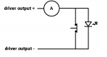
Iam currently working with an SLD1239JL-54 and using a DDL driver that has 6 volt input voltage 3 ohm resistor, and ranges from 11 ma to 390 milliamps. I want to modify my driver so that when I flick the on switch it will default to the ammeter telling how many milliamps my laser is set to and then when I push the momentary pushbutton then it will fire the laser. So far what I have tried is connecting the positive end of the ammeter to the momentary pushbutton which is connected in between the 3 ohm resistor and the column with the zenner diode, capacitor, and load. And the negative end of the panel ammeter right above the negative battery input. When I have been doing this, the panel ammeter seems to rapidly discharge the capacitor causing an unsafe drop in voltage. Can anyone suggest some schematics on how I can properly set a panel ammeter and momentary firing pushbutton to my DDL driver with out making the driver not work properly? Thanks.
 
Last edited:


Joined
Sep 12, 2007
Messages
9,399
Points
113
I think the easiest way to do this is use a normally closed pushbutton to short out the laser diode, and always have the ammeter in the current path. By default, current is shorted to ground so the laser diode is off. When the pushbutton is pressed, the short opens and current is allowed to flow through the diode instead.
 
Joined
May 13, 2014
Messages
7
Points
0
I think the easiest way to do this is use a normally closed pushbutton to short out the laser diode, and always have the ammeter in the current path. By default, current is shorted to ground so the laser diode is off. When the pushbutton is pressed, the short opens and current is allowed to flow through the diode instead.


I already got the pushbutton working but the panel meter still sucks all the power, can you please explain what you mean by "in the current path?". Where exactly does the negative and positive leads of the panel meter go?
 
Joined
Feb 18, 2013
Messages
744
Points
28
When measuring current, you have to literally break the existing circuit connections and physically integrate the ammeter into the circuit. I think that's what cyp meant by "in the current path", as it sounds like you're trying to just put one lead after the push button and the other to ground.

As far as I know, this won't work because the ammeter MUST be connected in between two points as the only path.
 
Joined
Sep 12, 2007
Messages
9,399
Points
113
Take a regular driver. Add a switch between the power source and the driver. Then add these two parts near the laser diode like so:

attachment.php
 

Attachments

  • ammeter_default.png
    ammeter_default.png
    4.9 KB · Views: 241

Benm

0
Joined
Aug 16, 2007
Messages
7,896
Points
113
This would basically work, but it does have a couple of severe disadvantages:

- the normally closed switch will have the driver drive a short circuit, using a lot of power, and possibly overheating the driver. The dissipation in the driver in the 'standby' position will be greater than that when operating with a laser diode load that drops a few volts.

- opening the switch would present a sudden and big load change to the driver. Depending on its design in my overshoot the set current as it ramps up the output voltage as best as it can before hitting the set current again.

The downside is that using the the DDL driver you have little alternative. If you used an opamp-based driver (say Merghart.com - Opamp based adjustable current source or anything like it), the voltage on pin 3 of the opamp can be measured and will show you the exact current setting (you need to divide by the value of the shunt resistor).

An even more elegant solution would be to use a togge switch, alternating pin 3 of the opamp between the adjustable resistors output and ground. This way you can know what current would be output before firing, and you'd have NO switches in any high-current path. This is more or less the same situation as getting a ttl or analog driver and switching it on via ILDA control.
You could now use a normally-open switch in series with the laser diode, so no power is wasted as long as the switch is not pressed. Note that this will work on this type of driver because it has no output capacitor that gets charged up and discharges into the laser diode when you press the button.

If you were to try this in real life i'd recommend putting a resistor (1k or so) in series with the diode/switch assembly such that the transistor has something to drive, and can kick into regulated operation more quickly/smoothly once you press 'fire'.
 
Last edited:
Joined
Oct 26, 2007
Messages
5,438
Points
83
Yeah, I don't like the idea of a switch near the diode. I know it's not a DDL driver, and this wouldn't be an exact current measurement, but what about something like a toggled current mirror/multiplier circuit so that you're not introducing a switch so close to the diode itself. The ammeter portion of the circuit could be set to not measure the actual current, but some fraction of it, when translated to the diode itself, so that you're not wasting so much power on the ammeter section -- and can read the current while the laser is discharging as well.
 

Benm

0
Joined
Aug 16, 2007
Messages
7,896
Points
113
I agree, and as i pointed out the most elegant solution would be to have the switch and meter connected to a low-current point in the system.

With the opamp driver this is quite easy. The only thing you need to do to is measure what input voltage results in what output current. This is actually just the value of the sense resistor, plus any wiring in its path which might be important if you use a low value (say 0.5 ohm) sensing resistor.
 
Joined
Sep 12, 2007
Messages
9,399
Points
113
Nonsense. The elegant solution is not having an ammeter in your laser in the first place.


Top