Welcome to Laser Pointer Forums - discuss green laser pointers, blue laser pointers, and all types of lasers

LPF Donation via Stripe | LPF Donation - Other Methods

Links below open in new window

ArcticMyst Security by Avery

MXDL Over 300mW! (LPM Reading Video pg. 2)


Gazoo

0
Joined
Jun 9, 2007
Messages
3,206
Points
38
Re: MXDL Over 300mW!

Ok.....but I am still baffled by this.... ;D I mean 300mw's with only 338ma's is baffling...to say the least :D
 

jayrob

0
Joined
Sep 21, 2007
Messages
9,862
Points
113
Re: MXDL Over 300mW!

Gazoo said:
Ok.....but I am still baffled by this.... ;D I mean 300mw's with only 338ma's is baffling...to say the least :D

I know what you mean! I swear it's true though. I will build another one without the silicon diode... Now, this driver is being powered with a single, 3.6 volt 18650 battery. (actually, it says 3.7 volts on the battery - Ultrafire) Please tell me again, (I know, you already told me before) what batteries are you using to run your 7135/open can with? Also, you said that the silicon diode could somehow be altering the voltage reading?
Jay
 

Gazoo

0
Joined
Jun 9, 2007
Messages
3,206
Points
38
Re: MXDL Over 300mW!

Jay,
You are probably seeing a voltage drop across the silicon diode which is soldered to your diode. The voltage drop across a silicon diode is around .7 volts. This could be why you are seeing the higher voltage...but you would need to try it to be sure. It does make sense because if you add .7 + 2.8 volts you get 3.5 volts.

I am powering mine with three nimh batteries. I also used a 4.5 volt power supply and get the same results....2.8 volts across the laser diode.
 

jayrob

0
Joined
Sep 21, 2007
Messages
9,862
Points
113
Re: MXDL Over 300mW!

I want you guys to see for yourself that this thing is really putting out over 300mW. I took this short video to show the LPM readings compared with a different MXDL laser...

P.S. I noticed that on my computer at work, I couldn't read the LPM settings on the video until I turned the contrast setting down a little on the monitor. My monitor at work has the little adjustment buttons right on the front of the monitor...
Jay
[media width=640]http://www.youtube.com/v/ByXlRm1zaJQ&rel=0&color1=0x006699&color2=0x54abd6&border=0></param><param name="wmode" value="transparent"></param><embed src="http://www.youtube.com/v/ByXlRm1zaJQ&rel=0&color1=0x006699&color2=0x54abd6&border=0" type="application/x-shockwave-flash" wmode="transparent" width="425" height="355"></embed> </object> [/media]

(Nice match burn video on pg. 6)
 

jayrob

0
Joined
Sep 21, 2007
Messages
9,862
Points
113
Ok...my curiosity got the best of me and I had to find out, so I cut one of the wires on the silicon diode and took some more measurements...
LPM MXDL open can.jpg

Now it is showing normally expected readings. I measured at the diode, 2.83 volts, 339mA and putting out 202.4mW.
Somebody please help me to understand why such a huge difference (over 100mW!) in power just because of this little 1N4001 silicon diode??

P.S. Gazoo, once again, you were right about your guess that it had something to do with the silicon diode. Now we have to figure out why?

P.S.S. Yes, of course I connected the diode back together! And it went right back up to the HOT readings. Gazoo, it peaked at 368.9mW!!! (I beat your 350mW, Ha Ha!) Lets see how long this baby lasts like this!...
Jay

(Hey Gazoo, it only showed that peak because it just happened to be pointed perfectly at the filter when I clicked it on...It stays around 310mW)
 

Gazoo

0
Joined
Jun 9, 2007
Messages
3,206
Points
38
I will have to try it...darn..you beat me..lol. Oh well. :'(

Anyway.. ;D I think the diode is interfering with the operation of the regulator..I do not know how or why or anything else.

If you were measuring something like 500ma's going to the circuit then I would be able to understand. Your current to output ratio is really throwing me for a loop.

I am going to try to put a silicon diode across my diode and see what happens. I will get back to you.
 

jayrob

0
Joined
Sep 21, 2007
Messages
9,862
Points
113
Gazoo said:
I will have to try it...darn..you beat me..lol. Oh well.  :'(

Anyway.. ;D  I think the diode is interfering with the operation of the regulator..I do not know how or why or anything else.

If you were measuring something like 500ma's going to the circuit then I would be able to understand. Your current to output ratio is really throwing me for a loop.

I am going to try to put a silicon diode across my diode and see what happens. I will get back to you.

Man, I hope it doesn't cook your diode. Then I would feel like it was my fault or something. But if you decide to do it, yes please report back with your measurements! Especially the current reading. I don't know how long this sucker is going to last like this, but wouldn't it be great if it somehow it just runs better with the higher voltage @ 340ish mA, and being an open can with a pretty good size heatsink, maybe it will be ok like this at 45 second duty cycles...
Jay
 

Gazoo

0
Joined
Jun 9, 2007
Messages
3,206
Points
38
Jay,
I am looking at the spec sheet and wiring diagram for the 7135. I think what is happening here is the silicon diode is shorting out the output of the regulator. So now I am hesitant to try it. I still can't explain how you are getting well over 300mw's of output with only 338ma's or so of current.

Here is something else you can try. Take the capacitor and silicon diode off of the laser diode and solder them in such a way we can see exactly how much current is going to the diode. You can solder them directly to the board for now or in between the wires.

I would like to know the current going to the laser diode by measuring between the circuit and the diode.
 

jayrob

0
Joined
Sep 21, 2007
Messages
9,862
Points
113
Hmmm....I'm going to have to build a different one then. Because the cap and silicon diode are connected right at the LD. And the module is 'pressed' into the aluminum heatsink. I only remove the modules if I fry the diode, because I have to press them out from the back side. Anyway, I have another open can so, you are talking about connecting the silicon diode and the cap on a circuit board, and then from there, just having wire leads going to the LD (like I have on my Ice Box) correct? Then we can take measurements between the cap/silicon diode and the LD. Is this what you mean? I guess I could easily take the module out of my Ice Box...just hate to mess with such an nice running machine...
P.S. Is there a way to simply test this 7135 driver and the cap/silicon diode set up without having to use one of the precious open can diodes?
Jay
 

Gazoo

0
Joined
Jun 9, 2007
Messages
3,206
Points
38
Yes... :) 
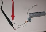
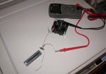
I think this would be helpful...there is no hurry. I still do not understand this, but like I said the 7135 is a totally different animal.

When you hook up the other open can, theoretically the current being measured between the power supply and the circuit should be the same as measuring the current between the output and the laser diode.

If it is the same and you are seeing over 300mw's, then I will still be confused. If it is not the same and you are seeing more current between the output and the laser diode...then my head will explode.. ;D

I wish there was someone here who knew more about this type of regulator and could explain what is happening :p
 

jayrob

0
Joined
Sep 21, 2007
Messages
9,862
Points
113
I think were still going to be scratching our heads here Gazoo...I soldered up a circuit for just a quick test. I know, it's not the correct way to test, but just for a quick look at voltage and current, it works. The readings are 4.07 volts and 341mA. So, the current going to the open can is less than 350mA, but the voltage is 3.55 on my MXDL. Some how the power is over 300mW. This little test circuit shows roughly the same current. Try it and see!...
Jay
 

Attachments

  • 7135_test.jpg
    7135_test.jpg
    24 KB · Views: 82

phenol

0
Joined
Oct 30, 2007
Messages
533
Points
18
jayrob said:
I think were still going to be scratching our heads here Gazoo...I soldered up a circuit for just a quick test. I know, it's not the correct way to test, but just for a quick look at voltage and current, it works. The readings are 4.07 volts and 341mA. So, the current going to the open can is less than 350mA, but the voltage is 3.55 on my MXDL. Some how the power is over 300mW. This little test circuit shows roughly the same current. Try it and see!...
Jay
4.07 volts :-? @ 3.7V?... uncanny for a linear CCS. are you sure your Si diode is ok? 1n400x are vy robust, yet... What about the tantalum cap? Maybe this circuit is plagued with parasitic oscillation occurring under different load conditions. These are just speculations a scope could support or debunk.
 

jayrob

0
Joined
Sep 21, 2007
Messages
9,862
Points
113
4.07 volts   @ 3.7V?... uncanny for a linear CCS. are you sure your Si diode is ok? 1n400x are vy robust, yet... What about the tantalum cap? Maybe this circuit is plagued with parasitic oscillation occurring under different load conditions. These are just speculations a scope could support or debunk.

These lithium batteries are actually at 4.2 volts when fully charged. 3.7 volts is when they are low and need charging.

Gazoo, I did another test with the little test circuit using a peltier as a load. This time I connected it to the DMM correctly. The readings were 4.06 volts @ 345mA. This tells us that the current reading that I got with the MXDL is accurate. No? I don't profess to know about electronics. But I know that the current with the MXDL is 338mA and the power reading is over 300mW! The voltage reading is 3.55 volts. This voltage reading seems to be the difference. Please build a little test driver like I did and help figure this one out! This is amazing!
Jay
 

Attachments

  • 7135_test2.jpg
    7135_test2.jpg
    33.5 KB · Views: 85

Gazoo

0
Joined
Jun 9, 2007
Messages
3,206
Points
38
Hello Jay,
I did want to point out that a lithium battery fully charged is 4.2 volts as you indicated. The nominal voltage is 3.6 to 3.7 volts. From there they discharge slowly. When they reach 3 volts is when they should be recharged. ;)

I will test the 7135 with a peltier this evening..I am very curious but I don't think I will be able to explain why this is happening even if I can duplicate it.


Top