

- Joined
- Jan 16, 2013
- Messages
- 34
- Points
- 0
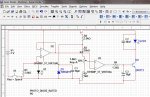
I made a copied green laser diode from Sam's. I'm not sure if I did things correctly I just copied the same exact schematic. Where should I connect the terminals of oscilloscope to the laser diode? and where do I connect the multimeter. Im working on an experiment (that I dont know how to do so I'm finding ways). I will be making a laser diode as is in the schematic but since I need an oscilloscope to view the wave formed by the laser diode (green) I used NI MULTISIM. thanks so much.
The one I made in the attachments is laserdiode.jpg and the schematic i copied is glpdrv4.gif. My multisim is also attached.
EDIT:
Okay I had it working now, but the wattmeter is my problem doesnt read power output! I connected the multimeter on Q1 (- and + of multimeter) and it reads okay. but there's no reading on wattmeter and the oscilloscope wave is also a problem shows square wave instead of sine wave, varies when I continually press switch (space)... need help and explanation.
I dont know the rules since I'm new so kindly bear with me. I didnt know this is considered as spamming. anyways i need urgent help thanks. also I attached a multisim file. please tell me what's wrong with the circuit i copied.
Attachments
Last edited:


