Welcome to Laser Pointer Forums - discuss green laser pointers, blue laser pointers, and all types of lasers

LPF Donation via Stripe | LPF Donation - Other Methods

Links below open in new window

ArcticMyst Security by Avery

help with my 405nm homemade laser

Joined
Feb 5, 2007
Messages
149
Points
0
hi im making a homemade violet laser and i need some help with the electronics,

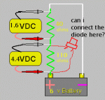
i am using a 405nm diode that takes 4.4V and 40ma im going to run it off 4 AA batteries in series (6v max) i was wondering if anyone here would know what i would need to get it to 4.4v\40ma im pretty sure ill need a 150ohm resistor to get it to 40ma but im a bit confused about the voltage.
ive found a picture and modified if to see if this is possible to avoid explaining it.
 

Attachments

  • resvd.gif
    resvd.gif
    5 KB · Views: 117


Joined
Jan 7, 2007
Messages
6,309
Points
83
NO -- That won't work.  You are putting an unknown Low impedance(resistance) parallel across another higher ohm resistor.  The low resistance of the diode will swamp out the effect of the parallel resistance and the diode will take most of the current. You could easily exceed 130 mA doing this -- STOP !!!

I'd use an LM 317 current source and bring the current up while monitoring the junction voltage. Watch both meters and take notes.
Test your current source with a ~5 ohm resistor - Don't use the diode for the range  set-up test.

Mike
 
Joined
Feb 5, 2007
Messages
149
Points
0
oh yea i understand, instead of going through the resistor it will go through the diode because it has less resistance.
im thinking of using 3 AA batts (4.5v) and having a 110 ohm resistor
 
Joined
Feb 5, 2007
Messages
149
Points
0
ive been reading up on LM317 voltage regulators and im either going to use a LM317 with variable resistors to controll voltage and current (i think) . is there other components i should be using in this curcuit? (there probably is)
if i cant get a driver set up with this method then ill probably buy a laser driver from here http://www.roithner-laser.com/Drivers.htm
 
Joined
Feb 5, 2007
Messages
149
Points
0
ok ive made a little driver board for the laser using a LM317 regulator it is the same as in the picture below exept the 60 ohm resistor is replaced with a 62 ohm because the shop didnt have 60 ohms.
 

Attachments

  • violet_laserdiode_driver.jpg
    violet_laserdiode_driver.jpg
    11.9 KB · Views: 224
S

SenKat

Guest
THAT looks like a nice circuit - Let's see if it passes the "Mike" test ! I do not have anywhere NEAR the same level of knowledge as he does - and value his opinions. It does lokk nice to me....now, with the 62Ohm rather than the 60Ohm - you can expect a TINY loss coming through - I assume....Mike - pitch in any time here !!! ;D
 
Joined
Jan 7, 2007
Messages
6,309
Points
83
Seems I saw this circuit on the CPF !!  Test the circuit befor putting in an expensive diode !!  

60 --- 62 ohms ??  That's within the tollerance band of the resistor - that's why the pot !!!  You will get about 1.5 to 2 volts drop across the regulator right off the bat - therefore a little extra input volts.  

Hey - just a thought -- Most of us have 5 mw red diodes strewn about. They run at about 40 mA. Find a scrap red LD and sacrifice it to the laser god !!

Mike
 
Joined
Jan 7, 2007
Messages
6,309
Points
83
Aaron--
The 62 ohm is OK to use. It's 2 ohm difference is less than the tollerance of the device anyway. The pot will compensate.
This is a constant current source. It limits the current but as you increase the current, the voltage across the load has to increase some. Ask Ohm, he made the law !!!

Mike
 
Joined
Feb 5, 2007
Messages
149
Points
0
haha ok ill go and ask him ;D
well i soldered everything on today and i messed up :'( it supplys 6V instead of 4.4V :mad: i used the pot to adjust it to 40 ma but ive done something wrong there is probably a short somewhere.
where the 2 wires cross over are they supposed to go over each other ie. the 15 ohm goes to the adjust pin and the 60 ohm goes ahead ? or just all join up? it dosent make much sense if they all join up because the current will go the way with the least resistance.


Top