Welcome to Laser Pointer Forums - discuss green laser pointers, blue laser pointers, and all types of lasers

LPF Donation via Stripe | LPF Donation - Other Methods

Links below open in new window

ArcticMyst Security by Avery

Help for a custom driver

Joined
Jan 9, 2010
Messages
15
Points
0
Hi everyone.
For the new red burning laser I want to make , I would like (to optimize the life of the diode, and the autonomy of the laser) to make a custom driver that would allow the laser not to be alwaws at full power.
For example the driver will output 50mA most of the time, and when I press a switch, it goes to 300mA, the time to burn something (or for another reason) and when it's finished, I release the swith and it goes back to 50mA.

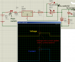
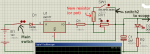
I tried to simulate a "modified" DDL driver ( I just added a switch ,see on the attached picture) on Proteus Isis ( a trial version) to see it it would work, but I have a problem. When I press the switch, there is a current "spike". I wondered if it was an issue with the simulation (we can only trust reality ^^ ), or if it will happen in a real circuit? I can't try because I have no oscilloscope, just a DMM.
On the picture I posted, the spike is not big but on another test I made, it was bigger (enough to kill a diode ?), and the problem is that I don't really know what changed between the two circuits :confused: and I would like my driver not to burn the diode, so I must be sure before I build it.
The funny thing is that if I remove the capacitor from the circuit, the spike disapears, whereas I thought it was there to prevent such spikes :gun: .

Has someone ever tried such a circuit, or could confirm (or not) the simulation ? Does someone sell a cheap and safer driver that has the feature i'm looking for ?
Or do I need to build a different circuit ? (it must be as small as possible, but without SMD :evil: )

Thank you, and sorry for my english :thanks:
 

Attachments

  • circuit.png
    circuit.png
    31 KB · Views: 208


Joined
Oct 24, 2009
Messages
2,738
Points
63
Theoretically you can add a switch wired in a series with the adjustment pot, add a couple capacitors to suppress any surges and it should be good to go.
 
Joined
Jan 9, 2010
Messages
15
Points
0
Theoretically you can add a switch wired in a series with the adjustment pot, add a couple capacitors to suppress any surges and it should be good to go.
The switch must be in series with the pot ? ( and not in parallel like in my schematic ?) Sorry if i misunderstand but it sounds weird: if it is in series, if the switch is open, no current can flow, can it ?
Thank you
 
Joined
Oct 24, 2009
Messages
2,738
Points
63
I cannot draw a schematic with my PC or I would gladly illustrate.

To lower the resistance of the pot, but not short it out, you would connect either a second pot or fixed resistor in a series with the switch, then connect the resulting 2 leads in parallel with the existing pot.

When the switch is open, the additional resistor is NOT included in the circuit, so the laser will output the MW that you pre-set with the pot.

When the switch is closed, the second resistor is now connected in parallel with the existing pot or resistor subsequently reducing resistance, bolstering current and raising the output.

Shorting the pot COMPLETELY by not including the second resistor in series with the switch will undoubtedly spike your diode and kill it.
 
Joined
Jan 9, 2010
Messages
15
Points
0
Ok so you mean something like that, plus some capas , i belive? (see the attachment)
 

Attachments

  • circuit.png
    circuit.png
    18.4 KB · Views: 169

drlava

0
Joined
Mar 7, 2007
Messages
1,152
Points
0
Concerning the spike, are those plots from the input or output of the driver? I would expect a spike if they are measured on the input side. However, note that there is a similar ripple when the circuit is turned off. You might want to decrease your simulation time step so that it is fast enough to follow the on and off transients without a big discontinuity in the solution.
 
D

Deleted member 8382

Guest
For your needs you need a total resistence of 25 ohms that must turn into only 4.2~ when pressing the switch. Just use a 20 ohms resistor and a 5 ohms resistor in series and make the switch to bridge the big one.

About the spikes, although I don't think they are going to damage your diode in any way (these are very little spikes), they can be removed by using a higher capacity capacitor at the output, 100uF would do the trick (I guess).

Yours,
Albert
 
Joined
Jan 9, 2010
Messages
15
Points
0
Concerning the spike, are those plots from the input or output of the driver? I would expect a spike if they are measured on the input side. However, note that there is a similar ripple when the circuit is turned off. You might want to decrease your simulation time step so that it is fast enough to follow the on and off transients without a big discontinuity in the solution.
It was the output of the driver, but as you said, i tried to change the simulation parameters and it showed a smooth output, without spikes. So i belive i can consider that it was a simulation issue, and that the problem is solved :).
Thank you for the idea

About the spikes, although I don't think they are going to damage your diode in any way (these are very little spikes), they can be removed by using a higher capacity capacitor at the output, 100uF would do the trick (I guess).
The problem was that ( before changing the parameters) the bigger the capacity was, the bigger the spikes were :gun: , so it sounded strange to me :D
But now the problem is solved, i will probably put a capacity of 22µF or so .
For the resistors, i haven't decided the current yet ( i haven't ordered the diode yet anywaw :D ), but i think i will be able to calculate the values.

Thank you for your help, the forum seems to be very friendly
:thanks:
 
D

Deleted member 8382

Guest
Always glad to help :)

Higher capacitors higher spikes? that sounds really strange! By the way, I missunderstood your first post, you were talking of power and I understood current. I made the calculations for currents, not for powers xD

By the way, I would set the "standby" power to 5mW, way safer ;)
 
Joined
Jan 12, 2008
Messages
3,290
Points
83
At 5mW the diode may not even laze. You probably want to go over the threshold lol.
 
D

Deleted member 8382

Guest
Well, there's for sure a current that makes the diode to deliver a safer power than 50mW. As I understand this project, it's like having an "aim" laser to then "fire", 50mW is way more than you need for that purpose xD
 
Joined
Aug 15, 2009
Messages
1,443
Points
48
The simulation only shows some ripple, zoom in more to see if there are any spikes. Shorting the pot works just as good as bridging it with a resistor because there's already a resistor in series, just make sure you have a big enough filter cap to surpress the transients of the LM317.
 
Joined
Jan 9, 2010
Messages
15
Points
0
Well, there's for sure a current that makes the diode to deliver a safer power than 50mW. As I understand this project, it's like having an "aim" laser to then "fire", 50mW is way more than you need for that purpose xD

Yes you're right but these values were only for the example. When i get the diode i will test which current will be safe (i think it depends much on the diode).

The simulation only shows some ripple, zoom in more to see if there are any spikes.
Yes on this simulation it's more like ripple, but on some others i did there was a clear spike, that's why i was worried. But again, it seems to be only a problem of simulation timestep, because when i lower it, the curve become smoother (more points are computed) and without any spike or ripple.
 
Last edited:


Top