erdabyz
0
- Joined
- Jun 30, 2008
- Messages
- 286
- Points
- 0
Just as suggestion.
Well... 4.7ohm is still too much. And germanium transistors tend to be expensive and they don't last very long. With a proper current sensing amplifier you can use 0,1 ohm or less precission resistors. Those devices have fixed gain so, instead of using a pot to adjust the gain as we would do if using a general pourpose op-amp, we use that potentiometer to divide the output voltage. A common op-amp would be great too but that requires some extra components that make the driver bigger... I have some TSC101A from ST electronics that would do the job.... but they require 4V to work so ...
I have to find some that would work at 3V or less and that way I could do a great driver for 8x's with LT1930's. They are the smaller and simpler switching IC's i've found that would be just perfect for driving 8x's from a single li-ion.
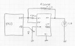
Oh, other thing I forgot, your configuration has a resistor in series with the diode, meaning that the driver would have to provide more voltage. So, if going to use a resistor in series with the diode, it HAS to be a very low value, so it won't increase too much the voltage the driver needs to supply.
Last edited:


")