Welcome to Laser Pointer Forums - discuss green laser pointers, blue laser pointers, and all types of lasers

LPF Donation via Stripe | LPF Donation - Other Methods

Links below open in new window

ArcticMyst Security by Avery

Driver Ideas. DC/DC stepup AND CCregulation

airy52

0
Joined
Jun 14, 2008
Messages
231
Points
0
I asked some questions but decided to start a thread here. I looked into a few components. I was thinking:

1: use a dc dc converter to up voltage(if you started with one or two AA's) and then use that higher voltage to run a constant current regulation circuit.

But I was talking to my dad and he thinks dc dc converters can control current too so i looked into it and found this chip
http://maxim-ic.com/quick_view2.cfm/qv_pk/2337
It says it has current regulation and it has enough step up to run from almost anything and a low Vin. What do you guys think? I am still reading the data sheet so i will post again when i finish.


woop

0
Joined
Nov 9, 2007
Messages
342
Points
0
yeah your dad is right. its been done here
http://www.laserpointerforums.com/forums/YaBB.pl?num=1212653254/60#63
here
http://www.laserpointerforums.com/forums/YaBB.pl?num=1209911140
and here (this one was the thread that sparked all the ideas, has heaps of info)
http://www.laserpointerforums.com/forums/YaBB.pl?num=1194375801


just for a bit of background info, switching power supplies regulate voltage by measuring it and comparing it to a internal reference though the feedback pin.
you can 'trick' the chip by giving it feedback from a sense resistor, so instead of regulating voltage, it regulates current.
because v=ir, the voltage across a resistor is proportional to the current, so its really easy to do. as long as your chip has a low feedback voltage (to minimize loss in the resistor)
otherwise you can amplify the voltage in the sense resistor and then feed it to the chip, this is what the lavadrive does.
 

woop

0
Joined
Nov 9, 2007
Messages
342
Points
0
and that chip you mentioned is constant voltage. it only has a MAX current of 800mA

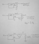
maybe this will help explain how a CC smps works (its basically the same as the lm317)
 

Attachments

  • P1020105.JPG
    P1020105.JPG
    35.6 KB · Views: 494

airy52

0
Joined
Jun 14, 2008
Messages
231
Points
0
so why can you not connect it up in the way for constant current? where on the datasheet is this specified. just for future reference. Thanks for youre reference by the way though, i dont quite understand it, i mean, i understand what resistors and ground are but not quite how it works logically. thanks...
 

woop

0
Joined
Nov 9, 2007
Messages
342
Points
0
well you could, but the feedback voltage is quite high (1.2V) so 1.2V would be wasted in the sense resistor, it just leads to less efficiency.
you could hook it up like the third diagram above, using an amplifier to amplify the feedback voltage. you could use any adjustable switching chip like this.

to explain the drawings above:
the first diagram is a normal voltage regulated smps, the two resistors form a voltage divider, so say the feedback voltage is 1V and you want 5V out, the voltage divider would drop that 5V to 1, so when the output is 5V, the feedback voltage is 1V

the second diagram is for constant current. the chip adjusts the output until it has the correct voltage on the feedback pin. because the voltage across Rs is equal to the current times the resistance, you will get constant current.

the third one is just like the 2nd but Rs is moved to the other side of the load. the amplifier only amplifies the difference between its inputs, which is the voltage across the resistor. this difference is then passed on to the feedback pin (it can be amplified at the same time)
the amplifier in this configuration is called a high side current amplifier
 

airy52

0
Joined
Jun 14, 2008
Messages
231
Points
0
i think you are missing the current regulation feature of this chip. you do not need to trick the vreg for cc. i think... il just step up to 5.5v then use current regulation on it and the voltage will figure it self out with the diode. the only thing i thought of is what others have mentioned: input voltage cannot be higher than volatage needed. even though i will be setting it to amplify to 5.5 from 2 aa's(3v) it will only be using probably 2.7 or so. So will this be a problem? since its a .7 min Vin should i just change the double a's to run parallel? Or am i way off track and this wont work ;)
 

woop

0
Joined
Nov 9, 2007
Messages
342
Points
0
oh yeah. just read the rest of the datasheet... so it is a constant current regulator, as well as a voltage reg

if its step up only, you will need to make sure the input voltage is lower than the LD voltage.

in this case it will regulate the current or the voltage, whichever one is higher. so even if you set it to 5.5v, if the current limit is 300mA, and your ld is sucking 300mA, it will limit the current, and the voltage will drop to the diodes forward voltage
 

airy52

0
Joined
Jun 14, 2008
Messages
231
Points
0
so is it step up only?(do i have to worry about the input/output higher lower voltage problem) :D hold my hand and read datasheets for me woop! !!


do you think its a good find? im going to design a circuit for it tomorrow. Maybe il be famous on here for the airy52 driver! lol Sweet.
 

woop

0
Joined
Nov 9, 2007
Messages
342
Points
0
airy52 said:
so is it step up only?(do i have to worry about the input/output higher lower voltage problem)
YES!
if a higher voltage is input, regulation will go out the window, and the diode will probably blow.
it is a good find, maybe not for reds, but for bluerays.
the only better find would be one of these with boost/buck capabilities
 

woop

0
Joined
Nov 9, 2007
Messages
342
Points
0
the max8625 doesn't have an adjustable current limit, it is set at 2A "The MAX8625A features current-limit circuitry that shuts down the IC in the event of an output overload."

and the lm3578 is only buck or boost, depending on how you set up the inductor.

i am sure the right chip must be out there somewhere, its just really hard to find
 

airy52

0
Joined
Jun 14, 2008
Messages
231
Points
0
stop crushing my dreams!!!!!!!!!!! damnit! i keep thinking i find the perfect one and theres one little thing wrong. its not fair!!! and the quest begins again. back to the maxim-ic website. Is there any other good sites that i should be looking on other than national? Thanks woop for doublechecking my ideas for me. Even though i already ordered samples of the 2 maxims... :(
 

airy52

0
Joined
Jun 14, 2008
Messages
231
Points
0
the first chip i posted is gonna work out failr well i think. it will make things MUCH easier with the current regulation instead of tricking vreg. the only problem i see is its step up only, so less efficiency than it could be, but still pretty high. but you can just put batteries in parallel instead, or it would make a superior blu ray driver.
 

IgorT

0
Joined
Oct 24, 2007
Messages
4,177
Points
0
Yeah, i'm very happy with the 3410. I'm getting >84% efficiency with it. And the TPS would allow using regular batteries.. Unfortunatelly, TI sent me the non adjustable version.. :(

This IC is not bad tho. It could be used for lasers easily. You just can't use a Li-Ion with reds. But a regular battery would work. And the efficiency would be better, than with the TPS i think.


Top