Welcome to Laser Pointer Forums - discuss green laser pointers, blue laser pointers, and all types of lasers

LPF Donation via Stripe | LPF Donation - Other Methods

Links below open in new window

ArcticMyst Security by Avery

DIY Homemade laser diode driver

Status
Not open for further replies.

chido

0
Joined
Dec 4, 2007
Messages
1,918
Points
0
That's called using a capacitor and a resistor to protect the diode design. ;D
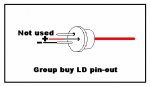
People who can't fit a driver or simply don't want to make one use a resistor to limit the current going to the diode and a capacitor to protect it from spikes. The only problem with this is that it's not regulated, so as the batteries get weaker so will the LD.


Joined
Mar 27, 2008
Messages
478
Points
28
chido said:
The only problem with this is that it's not regulated, so as the batteries get weaker so will the LD.

I knew I was missing something. The provided circuit keeps a constant current as the batteries get weaker (to a point)... I have no problem with the laser running in that way. In fact, I plan on running it on a variable dc power supply half the time anyways. I'm guessing that's the only drawback?
 

chido

0
Joined
Dec 4, 2007
Messages
1,918
Points
0
I can't guarantee it since I'm not an electronics expert and I haven't seen anyone discuss this matter before, but I'm guessing the only drawback is current regulation.
 
Joined
Jun 5, 2008
Messages
92
Points
0
I have to build two driver. One for a 200mw red laser diode, and the other for a not powerful blu ray diode (DT-0811). How can I calculate the resistor ohm need for obtain the desire mw?
 
Joined
Jun 13, 2007
Messages
5,410
Points
113
gregorio87 said:
I have to build two driver. One for a 200mw red laser diode, and the other for a not powerful blu ray diode (DT-0811). How can I calculate the resistor ohm need for obtain the desire mw?
To find the right value of resistor needed take 1.25 and divide it my the desired current (in amps). So say I Have an open can I want to run at 420mA, I take 1.25/.420 and I get 2.976. That rounds nicely to 3 ohms so that means I would need a 3 ohm resistor for my circuit. Then from there you can look at the power graphs to see about how much power your diodes are putting out.
 

chido

0
Joined
Dec 4, 2007
Messages
1,918
Points
0
Gazoo's canned response:

The LM317 is no mystery and very easy to work with. The following calculations always apply since it uses 1.25 volts for its reference voltage, and ohm’s laws don't lie. ;)

To calculate the resistor needed for a given current, take 1.25 and divide it by the current. So say you want to drive a SenKat diode with 250mA. 1.25 divided by .250 = a 5 ohm resistor.

Another way you could do this is to take 1.25 and divide it by the resistance. 1.25 divided by 5 = .250.

Next you will want to calculate the wattage of the resister needed. We know 1/2 watt resistors are common for use with the regulator. But to figure it out, simply take the 1.25 and multiply it times the current. 1.25 times .250 =.3125 watts.

The rule of thumb for the voltage going into the regulator is it should be 3 volts more than the voltage going to the diode. A SenKat diode running at 250ma's will have about 3 volts across it. Therefore a minimum if 6 volts is needed.
I recommend 6 NIMH batteries or 2 RCR123's for use with Daedal's driver.

This is why you need at least 8 volts to run the blu-ray. You will find when you have it hooked up, the voltage across it will be appx. 5 volts. But since it will only draw ~38mA, you can run it with a 9 volt battery.

EDIT: The bluray diode mentioned here is a PS3 diode.
 

roSSco

0
Joined
Dec 5, 2007
Messages
649
Points
18
chido said:
Gazoo's canned response:

The LM317 is no mystery and very easy to work with. The following calculations always apply since it uses 1.25 volts for its reference voltage, and ohm’s laws don't lie.

To calculate the resistor needed for a given current, take 1.25 and divide it by the current. So say you want to drive a SenKat diode with 250mA. 1.25 divided by .250 = a 5 ohm resistor.

Another way you could do this is to take 1.25 and divide it by the resistance. 1.25 divided by 5 = .250.

Next you will want to calculate the wattage of the resister needed. We know 1/2 watt resistors are common for use with the regulator. But to figure it out, simply take the 1.25 and multiply it times the current. 1.25 times .250 =.3125 watts.

The rule of thumb for the voltage going into the regulator is it should be 3 volts more than the voltage going to the diode. A SenKat diode running at 250ma's will have about 3 volts across it. Therefore a minimum if 6 volts is needed.
I recommend 6 NIMH batteries or 2 RCR123's for use with Daedal's driver.

This is why you need at least 8 volts to run the blu-ray. You will find when you have it hooked up, the voltage across it will be appx. 5 volts. But since it will only draw ~38mA, you can run it with a 9 volt battery.

EDIT: The bluray diode mentioned here is a PS3 diode.

I bet that has been posted 20 times in this thread. ::) Read people!!! :D
 
Joined
Jun 16, 2008
Messages
2
Points
0
I just built the same circuit for the laser diode which is a 16X single layer DVD burner; I using a virable resistor and the total resistance is about 10 ohums the current is already 128 mA. how come the laser is not as bright as a cheap 5mw laser pointer? I use a 9V battery already. ::)

the laser diode is tested by connect it with a resoncnce 1w LED circuit; will this demage the LD so that it is not working 100%? :'(
 
Joined
Jun 10, 2008
Messages
36
Points
0
Hi all,

Nice explaination but I'm still a bit of a noob so I was wondering if any1 could help me.
I plan to make a laser using a (roughly 200mw) Sony 16x dvd burner. Would this exact setup work shown in aaronX987's diagram with this diode? and would it still burn?


I appreciate any help or suggestions about other methods.
Thanks. [smiley=thumbsup.gif] [smiley=thumbsup.gif]
 
Joined
Feb 28, 2008
Messages
1,809
Points
0
sdfrycz said:
Hi all,

Nice explaination but I'm still a bit of a noob so I was wondering if any1 could help me.
I plan to make a laser using a (roughly 200mw) Sony 16x dvd burner. Would this exact setup work shown in aaronX987's diagram with this diode? and would it still burn?


I appreciate any help or suggestions about other methods.
Thanks. [smiley=thumbsup.gif] [smiley=thumbsup.gif]

Yes. & Yes.

this thread almost has 60,000 views! so close!!!
 
Joined
Jul 4, 2008
Messages
3
Points
0
2 questions:

1) Is rog8811's scheme in the first page correct?

(I think not, because it shows the "Photo" pin of the diode connected to the negative pole and the negative pin connected to the positive pole, but I would like an official confirmation)

2) To avoid possible heat damage to the laser diode, I was thinking about soldering a TO5 transistor socket to the rest of the circuit, then just plugging the laser diode into the socket. Is it a good idea?
 
Joined
Jul 24, 2007
Messages
2,749
Points
0
DevilMaster said:
2 questions:

1) Is rog8811's scheme in the first page correct?

(I think not, because it shows the "Photo" pin of the diode connected to the negative pole and the negative pin connected to the positive pole, but I would like an official confirmation)

2) To avoid possible heat damage to the laser diode, I was thinking about soldering a TO5 transistor socket to the rest of the circuit, then just plugging the laser diode into the socket. Is it a good idea?

1) Circuit drawing is correct, neg to pin with no black insulator, pos to next pin in anti-clockwise direction....

2) It is far better to solder onto the pins, should the socket come off you may zap your LD with the contents of the capacitor when it goes back on....

Regards rog8811
 

Attachments

  • LD_pin-out_003.jpg
    LD_pin-out_003.jpg
    33.1 KB · Views: 6,145
Joined
Jul 4, 2008
Messages
3
Points
0
1) Circuit drawing is correct, neg to pin with no black insulator, pos to next pin in anti-clockwise direction....
So, the incorrect one is the one uploaded by aaronX987?
 
Joined
Jul 24, 2007
Messages
2,749
Points
0
So, the incorrect one is the one uploaded by aaronX987?

They are both showing the same thing, they are both correct (though aaron shows red to neg for some reason) If you have an LD in front of you it is easier to understand.

Regards rog8811
 
Joined
Jul 11, 2008
Messages
16
Points
0
Cheers man, this is just the guide I was looking for, and excellent diagrams! Time to bust out my soldering iron!

:D

Thanks again!
 
Status
Not open for further replies.


Top