Welcome to Laser Pointer Forums - discuss green laser pointers, blue laser pointers, and all types of lasers

LPF Donation via Stripe | LPF Donation - Other Methods

Links below open in new window

ArcticMyst Security by Avery

DIY Homemade laser diode driver

Status
Not open for further replies.
Joined
Jul 7, 2007
Messages
492
Points
0
ok i have 2 questions

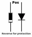
1. what is the polarity of these refractor diodes? does the ring represent the + or the -
http://www.diodes.com/datasheets/ds28002.pdf

and 2 deadel when you built the blu-ray circut did you put the diode in sequence or parallel with the LD to get rid of some of the voltage?

thanks alot in advance,
Mitch


Joined
Jul 24, 2007
Messages
2,749
Points
0
@ ruberband, the diode is used across the LD to protect it should you accidently connect the battery the wrong way round.

On the DRG below the + is marked for normal operation, you need to connect the pos to the other end in this aplication.

Regards rog8811
 

Attachments

  • diode01_002.jpg
    diode01_002.jpg
    25.8 KB · Views: 400
Joined
Jul 7, 2007
Messages
492
Points
0
thanks alot that cleared it up

1 more question
what does the diode do in normal operation and is it possable to to refract some of the voltage with these diodes?
 
Joined
Jul 24, 2007
Messages
2,749
Points
0
a diode will drop the voltage by 0.7v when used in series with the LD

The common use for them is in a rectifier bridge circuit, 4 of them converting AC to DC, they can do this because they only allow the current to flow in one direction.

Regards rog8811

*Edit just reread your last, I misunderstood your meaning, at least igor knew what you meant;)
 

IgorT

0
Joined
Oct 24, 2007
Messages
4,177
Points
0
rubberband said:
thanks alot that cleared it up

1 more question
what does the diode do in normal operation and is it possable to to refract some of the voltage with these diodes?

What these diodes do, is let the current flow in one direction ONLY.

This way you can put the diode in the beginning of the circuit and it prevents damage to the circuit in case you connect the battery the wrong way...

With the 4001-4007 there is a voltage drop of 0.6V (if this is what you meant with refract).

So if you use a rechargable LiPo for example, that has 3.6V, and use such a diode for reverse polarity protection, on the other side of the diode you'll only get 3V (due to the 0.6V drop in the diode). These 3V is actually perfect for the operation of an LD, but you'd still need at least a resistor, to limit the current going through the laser diode.

The best way is to use a fixed resistor and a potentiometer in series. The resistor would limit the maximum current, and by turning the potentiometer, you could adjust the current.

If you'd use such a setup, it would be a good idea to also include a capacitor in parralel with the LD, to prevent voltage spikes.. It is a good idea to short the capacitor, before connecting it to the LD in case it has any charge in itself...


I hope this helps.. If you need more info, or don't understand something, ask.


EDIT: I just noticed this question was already answered.. Sorry...
 

IgorT

0
Joined
Oct 24, 2007
Messages
4,177
Points
0
Daedal!

One more question...

In my previous post i described a simpler LD "driver" circuit...

3.6V imput, just a capacitor across the LD to protect from voltage spikes, a max current limiting resistor and a 100Ohm pot for adjusting the current and a diode for polarity reversment protection and also to reduce the voltage to 3V...

This way, i could use three NiMh cells. I would like to use as little NiMh cells as possible, and i think it should work.

What do you think about such a setup?

What are the pros and contras in comparing this circuit to yours?


The way i see it:
Pros:
- Less cells needed
- current still regulated
- LD protected from voltage spikes
- Simpler / smaller
Cons:
- Cant use a different voltage power source
- ?

What else?


Thanks!


Igor
 
Joined
Jul 7, 2007
Messages
492
Points
0
igort
thanks man that cleared up alot.

i already built a couple of deadels drivers i was just wondering about the voltage drop of those diodes inorder to properly drive a blu-ray diode.

i was also wondering if you put 2 diodes in sequence with 2 RCR123 batteries that both put out 3.6 volts each then you would be able to use deadles circut with the lm317 propely and drive a gb laser diode.

thanks
Mitch
 

danq

0
Joined
Sep 18, 2007
Messages
835
Points
18
Igor, you're going to also have a voltage drop across the resistor/pot. How much depends on the current.

If you're running the circuit at 40mA (milliamps) then the voltage across a 100 ohm resistor will be 4.0 volts!

The formula is Volts = Current X Resistance (V=IxR or E=IR etc...)
in this case for your pot, that's .040 X 100 = 4.0 volts

At 3.0 volts, in order to get 40mA current the total resistance of the circuit can only be 75 ohms - that includes the laser diode.


One approach to simple supply design here would be to calculate the effective resistance of your laser diode at its operating voltage and currrent, using the above formula (Ohm's Law). Then when you get that figure you'll be able to figure out the maximum resistance of the driver circuit. It's not quite that straightforward because the LD isn't just a resistor; but in this case it will work as a rough guideline.

So, IF you have a Blu-ray LD that runs at about 4.5V and 40mA:

LD effective R = 4.5 / .040 = 112.5 ohms

If your supply voltage is 4.5 V you're not going to have any 'room' for current limiting or protection diode. Four NiMh doesn't get you much farther.

Starting with 6 volts though, or better, 7.2:

Total R can now be 7.2 / .040 = 180 ohms

Take off .6 V for the protection diode, get 6.6V, remaining R = 6.6 / .040 = 165 ohms

165 ohms (total) - 112 ohms (LD) = 53 ohms for your circuit to put out 40mA.

now you can put in a 100 ohm pot and a 10 ohm resistor with your diode and run your Blu-ray between about 30 to 54mA.

Remember - these are rough figures because of the assumption about the LD's effective resistance! You should monitor the current at first by measuring the voltage across your fixed resistor as you go. And don't forget that capacitor.


I think I got this right - Rosie the Wonder Dog is interfering with my concentration - but I'm sure any needed corrections will come swiftly! ;)

(edited to correct errors; found none; re-instated) ::)
 

IgorT

0
Joined
Oct 24, 2007
Messages
4,177
Points
0
rubberband said:
IgorT
thanks man that cleared up alot.

i already built a couple of deadels drivers i was just wondering about the voltage drop of those diodes inorder to properly drive a blu-ray diode.

i was also wondering if you put 2 diodes in sequence with 2 RCR123 batteries that both put out 3.6 volts each then you would be able to use deadles circut with the lm317 propely and drive a gb laser diode.

thanks
Mitch

Since you would get 7.2V, you could put two diodes in series in front of the circuit.. It would definatelly work the way you imagined. But it might not even be neccesary, since the 317 does the current regulation. It depends on how it's set up...


I can't tell you for sure tho, since i haven't built and tested the circuit yet. I made a simpler one instead (the one i described to in my previous reply). I feed it 3.6V and it gives out 3V and i can regulate the current with the pot.

But if you don't have enough experience with electronics and have a multimeter, the Daedals circuit might be better. Still, in both cases, you'd have to adjust the current for different LDs.

For now i'm gonna stick to the simpler circuit, just because i can use it with a single cell LiPo or three NiMhs..

It'll work with all kinds of LDs, but as i said above, for different ones, you have to measure and set the pot for the correct current..


For the blue one for example you'd need A LOT LESS current. But i don't know how much. Do you have any specs? What is the usual current for 10mW LDs?


If you want i can send you the circuit diagram i am using currently.


Good luck!


Igor
 

IgorT

0
Joined
Oct 24, 2007
Messages
4,177
Points
0
danq said:
Igor, you're going to also have a voltage drop across the resistor/pot. How much depends on the current.

danq!

I work with electronics proffesionally, so i allready know most of the stuff you wrote. I just don't know much about LDs in general..

So thanks for the info about the LDs internal resistance and other stuff!

I allready tested my circuit and it works fine, but it only went up to 120mA. I had to reduce the current limiting resistor to get higher than that.

I will leave the pot there, in case i need to drive lower power LDs.. Like the blue ray one i'm getting...


Otherwise, thanks for the info! Any imput is apreciated..


Have fun!


Igor


P.S. Currently i removed another LD from a 16x writer.. Unfortunatelly they are soldered onto some nickle plated copper plates (that probably work as heatsink in the original assembly) so they're not easy to get out... Trying to unsolder it would probably kill it from all the heat..

So i decided to leave it in the brass plate for now. This will then be attached to a Peltier TEC for additional cooling and a collimator mounted in front..

Wish me luck!
 

danq

0
Joined
Sep 18, 2007
Messages
835
Points
18
IgorT said:
danq!

I work with electronics proffesionally, so i allready know most of the stuff you wrote. I just don't know much about LDs in general..
oops - sorry! ya never know who's on the other end... there's such a wide range of technical experience here - from "what's a wire?" on up way past me! I'm often amazed at what some people here are doing - and grateful for their patience and willing to share and help us less experienced.

:)
DanQ
 

IgorT

0
Joined
Oct 24, 2007
Messages
4,177
Points
0
danq said:
oops - sorry! ya never know who's on the other end... there's such a wide range of technical experience here - from "what's a wire?" on up way past me! I'm often amazed at what some people here are doing - and grateful for their patience and willing to share and help us less experienced.

:)
DanQ

That's ok.. I once explained someone in great detail, how to solder. Then he told me he has 30 years of soldering experience.. His only problem is bad eyes..  ;D

So i know what you mean.. ;)
 

IgorT

0
Joined
Oct 24, 2007
Messages
4,177
Points
0
danq said:
[quote author=IgorT link=1185701612/435#444 date=1193425330]30 years of soldering experience.. His only problem is bad eyes..  ;D
add shaky hands and that was me...  :p

DanQ
[/quote]

So you have shaky hands, bad eyes and 30 years of soldering experience? Oh and not to forget, are interested into reversing the trim knob on a FlyTech Dragonfly?

Are you sure that was you? ;)


BTW: I am into R&D. I develope new devices, sometimes old ones, that are not in production anymore, sometimes even some crazy stuff that other people woldn't poke with a ten foot pole, just to make the customers happy...

The part i like most is figuring out how it's all gonna fit together. The part i like least is putting everything into an enclosure in the end, or even worse, creating a special and complicated enclosure myself, by hand.. But in such extreem cases i charge 60$US per hour..


Then i go and build some more electronic devices for fun...  :D Guess what it is currently...
 

IgorT

0
Joined
Oct 24, 2007
Messages
4,177
Points
0
danq said:
Remember - these are rough figures because of the assumption about the LD's effective resistance! You should monitor the current at first by measuring the voltage across your fixed resistor as you go. And don't forget that capacitor.

I would be very greatefull for some additionall info about this.

You stated the LD's resistance as 112Ohm. Was that calculated from somewhere, or measured? Or a combination of both? :)

And another thing.. You mentioned monitoring the current by measuring the voltage across the fixed resistor.. I've read about this somewhere else, and that it's preffered to putting the multimeter in series with the LD.. Could you explain this a little better please?
Why is it preffered and how exactly do you do it?


Thanks!


Igor
 
Status
Not open for further replies.


Top