- Joined
- Sep 6, 2007
- Messages
- 51
- Points
- 0


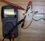
Mountaineer said:Here are the pics of my circuit. I have it running a 5mm, 2.6V, 28mA LED.
The first one is just of the circuit powering the LED. The battery is on the right out of the picture.
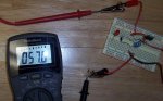
The second is of it the voltage measured on my DMM with the leads at the LED. It's showing 2.339V (the battery is quickly dropping in voltage it was at about 2.45V last time.) Measured like this, the current is 57mA.
The third picture is of the current being measured straight from the circuit without being connected to the LED. Like this, it's at 57mA and 4.63V.
I figure I'm supposed to measure it with it hooked up to the LED?!?! If that's right, then I'm getting ~41[ch8486] (2.339V/.057A) and 133mW (2.339V*.057A). Does the rest of the circuit besides the resistor create about 19[ch8486] of resistence (41-22) :-?? If anyone has any questions/suggestions that could help me out on this or if you need more pictures, let me know, I need all the help I can get. I can answer your questions/post more pics in a couple of hours if needed (I have to get some mergers & acquisitions homework done - ouch! [smiley=cry.gif]) Thanks in advance.
") . That's what I use
. That's what I use I dont know if this would help but i thought id post it. you probably alrdy know all of this and the questions on there... http://sol.sci.uop.edu/~jfalward/seriesparallelcircuits/seriesparallelcircuits.html it helped me a lil bit but i am a noob!Mountaineer said:Thanks for the help guys. Would a 4.7ohm resistor give me 266mA (1.25V/4.7ohm), and is that too much? What would the mW be then? I'm still trying to figure out all the [highlight]maths and stuff involved in figuring this out.[/highlight] Kinda makes a guy's eyes want to cross... Sorry if all this is beating a dead horse, but I'm just not quite getting it yet. Thanks again chimo and DDL [smiley=dankk2.gif], now it's time for me to take my helmet off and go to bed, I've got to catch the short bus early in the morning haha
i started figuring out how this works and I finished the driver last night! philguy said:Well, I came to this thread to complain (nah, rather ask for help politely) because my circuit doesn't work.
Problem was, I thought "1-2-3" on the circuit on p.1 referred to legs 1,2,3 on the LM317. Unfortunately, with the LM317 T, this is not the case, instead of "in-adj-out", it is "adj-out-in". Now gotta go and see if it works
Just if that helped anyone.
Mountaineer said:Would a 10uF 16V capacitor handle the spikes OK? I don't figure it will since the recommended capacity is almost 5X that, but I just thought I would make sure. The reason I'm asking is because I'm trying to find a tiny capacitor to fit into the Aixiz module that I can get at the local Radio Shack. Would this one work?:
http://www.radioshack.com/product/i...ssion=1&numProdsPerPage=100&parentPage=family
Thanks!
toked323 said:daedal i hooked up the diode to the circuit but it shines dim but i put and LED on and bam light up the blue LED when i added the 5 ohm did it need to be in series or paralel