Welcome to Laser Pointer Forums - discuss green laser pointers, blue laser pointers, and all types of lasers

LPF Donation via Stripe | LPF Donation - Other Methods

Links below open in new window

ArcticMyst Security by Avery

Building a driver.

Joined
Oct 24, 2009
Messages
2,555
Points
48
yeah i just found a program that let me plop things down and connect them so it looks like i know what i am doing but i have no idea!
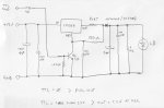
Also update my ttl drive i think is working it outputs 100ma and when i apply a -5 to the ttl input it turns off.
So i think i got some thing working for once, if i use a +5 volt to the input nothing happens.
and my dac only puts out +5 also when i hooked up the -5 line to the ttl input Q2 got very warm so i dont know if it turned off due to making a short or what.
So something is wrong could some one look at the second schematic for me i only see 1 ttl input but where does the ground go to? it should be off at 0v and on at 5.
 
Last edited:


HIMNL9

0
Joined
May 26, 2009
Messages
5,318
Points
0
TTL ? ..... i was thinking you needed an analog modulation .....

Anyway, if you want to try with TTL, this is the easiest way that i know for use a current regulator drive and modulate it TTL .....

attachment.php


RSET is the regulation current resistor, you need to set it for the specific current that you want for each one of the diodes ..... the TTL input will accept practically all the levels, if you don't put any input on it, the driver is on, when you put anything over 2V on it, the driver become shut down ..... due to the nature of the LM317 family, is impossible to go to zero volts, at the output, but with the diode in serie, it's ininfluent, cause it's always under the VF of the LD .....
 

Attachments

  • ttl-mod-current-01.jpg
    ttl-mod-current-01.jpg
    95.7 KB · Views: 4,314
Joined
Oct 24, 2009
Messages
2,555
Points
48
i can use both. but it seems i will need to go and buy new op amps for this to work.
But with the stuff i have now i should be able to make a ttl drive just to keep thing moving along.
Well okay but ttl needs 2 wire right?
But i only see placement of one of them where does the other one go.
Just to the ground right?
I do have a lm324 op amp its a quad so could i use this to drive all 3 drivers?
 
Last edited:

Benm

0
Joined
Aug 16, 2007
Messages
7,896
Points
113
Does that LM317 circuit actually work? It seems okay, but i wonder if it will like being modulated at kHz speeds all that much.

Personally i'd ditch the 1 uF cap over the laser diode... but also consider shorting the laser diode for modulation instead of mucking with the adjust pin signal. The LM317 is built to tolerate variable loads, more so than variable adjust voltages.

Building a TTL driver isnt that hard anyways. I've done one on a prototype board that just acts as a comparator for the dc-modded soundcard output to an adjustable voltage. The output drivers base current to a transistor current source, and it actually works fine, though i havent checked for accuracy in the current yet.
 
Joined
Oct 24, 2009
Messages
2,555
Points
48
The lm317 seems to work i am hooking up my galvos atm and going to test it out. i would still love to get analog but this is good for now but not done.
ohh the npn transistor gets very warm borderline burning if its blanked for too long i take it this is normal for such a thing?
 

HIMNL9

0
Joined
May 26, 2009
Messages
5,318
Points
0
@ kiyoukan: yes, the ground is in common with TTL modulation (is always considered this way, if not specifically stated otherwise) ..... the BC337 transistor can become a bit hot, but if you keep the driver in "OFF" state for long time, you can exchange the 220 ohm resistor with a 560 or 680 ohm, it must work the same ..... and if you use a 12V or higher modulation, instead 5V, you can also exchange the 1Kohm resistor that is connected between the base of the transistor and the mod input with a 10 Kohm one, but this is not a problem .....


@Benm: i have used this system til 500Hz, 600Hz maximum, til now, so don't know exactly how much it work good at multiple kilohertz speeds (means, if the fronts of the modulated output are very quickly switching on/off) ..... if you need a quick modulation, yes, is better remove the 1uF capacitor and left only the 100nF one.
 
Joined
Oct 24, 2009
Messages
2,555
Points
48
okay so the drive you posted works,
i can get it to blank when using laser boy but only when i invert the whole the wav file, but when i do that the blanking is reversed.
But when it is normal it does not blank at all.
I have a feeling this is a setting in laser boy but i cant find it.
When its normal he output of the blue channel is -1.279 and when inverted its 1.279
So i need it not to be negative but i cant find or know how to do this.
Thanks so much for all your help so far i see a very nice light at the end of the tunnel. And look it can spell my name!
 
Last edited:

HIMNL9

0
Joined
May 26, 2009
Messages
5,318
Points
0
Sorry, i don't have laserboy (i think is only for linux) so i can't test it ..... but, if it look like other programs similars, in TTL mode you must have an output that can be used for modulate the laser, and it must go from 0 to 5V (or 3,3V, that is enough, anyway), and the TTL modulation must have some setting for invert it (i mean, 0=on or 1=on setting) ..... but still positive, compared with ground .....

I really don't figure how a TTL modulation can be negative ..... with laserboy, from where you get the TTL modulation ? ..... i mean, on the PC, from what output you get the TTL modulation signal ? (i'm just wondering maybe you need an inversion of signal somewhere, but still trying to imagine why you get a negative signal :confused:) ..... do you have any schematic for the outputs ?
 
Joined
Oct 24, 2009
Messages
2,555
Points
48
Just a normal soundcard and correction amp.
When i play the max file everything goes to perfect lasers turn off 5V max and when no signal 0V.

laserboy is for windows as well. i would use lfi but it no work. and i don't know of an free software that will work, would hate to spend the money just to find out my machine does not work with it.
 
Joined
Oct 24, 2009
Messages
2,555
Points
48
Great news lfi player has started working on my machine.
So i got this driver working.
I would still love to go to analog, but i can live with ttl for the moment.
if the components i have listed above could be used in some way i would be very greatfull.
I am not looking foward to buying a ton of new parts.
 

Benm

0
Joined
Aug 16, 2007
Messages
7,896
Points
113
LFI should work, but it important to get the settings right.

For me, the first mistakes were: selecting the wrong soundcard, and not checking the laser 'on' in the program. The laser is off by default, so it took me quite a while to figure out where exactly that nice display was going to ;p
 
Joined
Oct 24, 2009
Messages
2,555
Points
48
i was told it was my laser on button but only after i re downloaded it and it somehow came checked and started working before i even knew it.
i loled just one button the whole time..... then tears as my lasers lit the room, such a sight.
OHH well what ya gonna do right.
 

Benm

0
Joined
Aug 16, 2007
Messages
7,896
Points
113
You're not the only one... it took me asking on the forums what was wrong as well before figuring that button out.
 
Joined
Oct 24, 2009
Messages
2,555
Points
48
So the white fusion driver is analog and looks simple enough is there any way to get a schematic for it?
it is perfect in every way just dont care for it to have the chip but everything else looks good.
Maybe just buy the schematic off him or just a blank board to make a scheematic of my own?
:poke:
 

HIMNL9

0
Joined
May 26, 2009
Messages
5,318
Points
0
not exactly "analog", it's a PWM modulation where you change the duty cycle for change the luminosity ..... you can use a 555 IC for that, without too much problems ..... the white fusion uses a programmed PIC that drive the 3 regulators in PWM for all the effects.


Top