LPF Donation via Stripe | LPF Donation - Other Methods
Links below open in new window
ArcticMyst Security by Avery


You are using an out of date browser. It may not display this or other websites correctly.
You should upgrade or use an alternative browser.
You should upgrade or use an alternative browser.
Boost driver ideas...
- Thread starter GooeyGus
- Start date
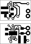


woop said:and here is toked's board resized :")
Thanks woop, I made some of your circuits, they are small.
So i am goiong to re-design mine. I like yours because you minimized the waste of copper.
Also you were right, with my circuit operating the copper tracks heat up,
not to much but it can be better.
yes there is.toked323 said:Woop, I was wondering is there any BIG difference between the tsp61200 and the tsp61202
I have the tsp61202
the tps61200 has a feedback reference of 0.5V, the 61202 has a feedback reference of 5V
the 61201 and 2 are supposed to be pre set constant voltage regulators, the 61200 is the adjustable version
basically you can't use the 01 and 02 versions for constant current.
so in your design, it looks like you where aiming for constant voltage. how where you planning to regulate current?
Hey I've been lurking around and had some questions. My dad is an EE and I was thinking about designing my own schematic for a laser diode driver. lavas seems to be the best, is their a schematic for it anywhere or any way to make it on my own? how is he achieving such high efficiency????
my idea was to use a dc/dc converter to up the voltage of 1 or 2 AA's and then use the lm317 for current regulation but that sounds like it wont be too efficient. This new chip you guys are discussing sounds good but lavas seems to do better than anything i see. I really wish I could get his schematic and make my own. I just cant afford to buy it, I dont have a lot of money. So anyone got any comments or ideas about what i said?
my idea was to use a dc/dc converter to up the voltage of 1 or 2 AA's and then use the lm317 for current regulation but that sounds like it wont be too efficient. This new chip you guys are discussing sounds good but lavas seems to do better than anything i see. I really wish I could get his schematic and make my own. I just cant afford to buy it, I dont have a lot of money
. So anyone got any comments or ideas about what i said?his is just like this design but it has a high side current sense amplifier, the 2nd chip on the board. this makes it easy to adjust current with a pot and leads to slightly higher efficiency (because of less loss in the current sense resistor) it also allows the diode to be connected to ground, because the current measurement goes on on the 'high' side of the diode
that is basically the only difference.
you can include an amplifier in this design, like the lt6106.
http://www.linear.com/pc/productDetail.jsp?navId=H0,C1,C1154,C1009,C1077,P37671
I was going to do this anyway.
the reason the lavadrive has such good efficiency is because its a switch mode power supply, instead of limiting the current by burning extra voltage as heat, it stores energy in a coil and converts voltage with very small losses.
obviously losses are higher when the power supply is a 1.5V cell, because larger currents are involved, but when you run them off 3.6V, efficiency is very good.
there is nothing magical about the lavadrive.
when i design a version with the high side amp, i will post schematics.
i want this to be an open source driver. although it is really quite simple
- Joined
- May 7, 2008
- Messages
- 545
- Points
- 0
so any chance someone will be starting a For Sale thread and trying to sell some of these off?
because i haven't gotten around to it yet. i am in the middle of uni exams, which will be over tomorrowairy52 said:why are you not incorporating the high side amp into the schematics above? all you said about it is good.
yes there is.woop said:[quote author=toked323 link=1212653254/60#66 date=1213455061]Woop, I was wondering is there any BIG difference between the tsp61200 and the tsp61202
I have the tsp61202
the tps61200 has a feedback reference of 0.5V, the 61202 has a feedback reference of 5V
the 61201 and 2 are supposed to be pre set constant voltage regulators, the 61200 is the adjustable version
basically you can't use the 01 and 02 versions for constant current.
so in your design, it looks like you where aiming for constant voltage. how where you planning to regulate current?[/quote]
Well the spec said it can deliver currents up to 800ma? I was gonna use a 1.8Mohm resistor and a 20k trimmer pot to regulate the current. But as far as I know according to the graphs the current and voltage pretty much stays put and doesnt rise much at all pass what it is set to.
I was going to try the LT6106 but the ZXCT1009 looks good.toked323 said:Well i just ordered some more free samlpes of the tsp61200, But any idea of what chip or IC to use to have LD- and Batt- common ground?

airy52 said:hey woop is an amplifier really neccasary in the rsense part of the circuit like you mentioned to me. its only .5 volts.... oh and i notecied l - vin is a inductor. what does that do? or whats it for? :-[ im learning...
the only reason you would want the amp is so you can connect the ground of the LD to ground. otherwise you can't have the two contacting each other, this makes it hard to heatsink lasers when you have it mounted in a metal flashlight body, where the body is connected to the battery
an inductor is a coil. its complected... its a flux capacitor
the core of a smps.http://en.wikipedia.org/wiki/Inductor
An inductor is bassically wounds of copper either around a steel or ferrit core, the more wounds the more uH(microhenries), How it helps with stepping up voltage? well i dont no. I have a few MAX1674 step up voltage regulators, I am pretty sure it doesnt use an inductor or maybe its my other MAX chip? I don't know. Now woop, Incorporating those chips you mentioned, they could fit on my board because i can almost fit 2 complete of my boards in my modules, so this may work well.
