The setup I'm talking about is adjustable voltage, and current is easy enough to limit with a simple trimpot; and you'll still end up with a driver with ~90% efficiency. The actual components aren't that bulky (there are a total of maybe 8 components). It should fit together fairly compactly.IgorT said:Not to mention, that it's a constant voltage boost circuit. The adjustable version could be adapted to regulate the current, but it would require even more components and it would have a lower efficiency.
As a constant voltage setup it's really not safe for laser diodes. At a certain constant voltage, every diode will draw a different current, even if they are of the same type. So it has to be adjusted for each of them separately and then it has to be set lower than max safe current, because the current will climb as the diode heats up. With constant current, every diode will draw the same current, even if they are completely different.
It's better to go with an IC, that is designed to do constant current. There are many options, but going with one, that is not meant for this and modifying it is not really useful. It would be more complicated to make it, and it would be bulkier in the end and it would not work as good as something meant for this purpose.
LPF Donation via Stripe | LPF Donation - Other Methods
Links below open in new window
ArcticMyst Security by Avery


You are using an out of date browser. It may not display this or other websites correctly.
You should upgrade or use an alternative browser.
You should upgrade or use an alternative browser.
Boost driver ideas...
- Thread starter GooeyGus
- Start date


rkcstr
0
- Joined
- Dec 1, 2007
- Messages
- 1,368
- Points
- 0
IgorT said:At a certain constant voltage, every diode will draw a different current, even if they are of the same type. So it has to be adjusted for each of them separately and then it has to be set lower than max safe current, because the current will climb as the diode heats up. With constant current, every diode will draw the same current, even if they are completely different.
That's exactly what I ran into when I made up some boost circuits for my blu-ray diodes using a 5V boost voltage regulator... I had a 20ohm trimpot on there in series so that the current could be adjusted for the diode. But, I noticed that running it for about a minute the current tended to slowly creep up, after a few minutes it was about 10-20% higher than the initial current. I originally had set current on some to around 40mA and after time it would creep up past 45mA (approaching 50mA), which I think damaged the diodes, because they started having weak output and the yellowish/red artifacts :-/ This is mainly why I never started selling them... didn't want anyone coming back saying my driver killed their diode, then DrLava came out with his Lavadrive and cornered the market ;D
rkcstr said:[quote author=IgorT link=1212653254/12#15 date=1212789867]At a certain constant voltage, every diode will draw a different current, even if they are of the same type. So it has to be adjusted for each of them separately and then it has to be set lower than max safe current, because the current will climb as the diode heats up. With constant current, every diode will draw the same current, even if they are completely different.
That's exactly what I ran into when I made up some boost circuits for my blu-ray diodes using a 5V boost voltage regulator... I had a 20ohm trimpot on there in series so that the current could be adjusted for the diode. But, I noticed that running it for about a minute the current tended to slowly creep up, after a few minutes it was about 10-20% higher than the initial current. I originally had set current on some to around 40mA and after time it would creep up past 45mA (approaching 50mA), which I think damaged the diodes, because they started having weak output and the yellowish/red artifacts :-/ This is mainly why I never started selling them... didn't want anyone coming back saying my driver killed their diode, then DrLava came out with his Lavadrive and cornered the market ;D[/quote]
You need to know the resistance in order to set it properly. If you know the voltage, then you use the equation V/I=R (where I is current), and set the trimpot to that resistance.
rkcstr
0
- Joined
- Dec 1, 2007
- Messages
- 1,368
- Points
- 0
mikewitt said:You need to know the resistance in order to set it properly. If you know the voltage, then you use the equation V/I=R (where I is current), and set the trimpot to that resistance.
Yes, I know...
The problem wasn't that I couldn't set the current. I DID set the current to start, but as the diode warmed up, resistance decreases, current increases... what IgorT was saying that the current will drift as the diode temperature changes.
The fact is, the current wasn't regulated, only the voltage was... using Ohm's Law if voltage is held constant and resistance changes, so will current.
- Joined
- Oct 26, 2007
- Messages
- 5,438
- Points
- 83
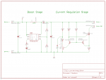
I was thinking a circuit like this might work. It has two stages, a boost stage and a current regulation stage that uses a MOSFET rather than a resistor for regulating current. I adapted the circuit from an LED dimming circuit. The benefit is that the pot will regulate the current from zero to some max value determined by R4, giving it a better swing. I suspect the current regulation stage could be used with a straight battery if you put a capacitor and diode there to prevent the current spike. Perhaps with this one the power for the current regulation resistors could come from before the boost stage.
Attachments
rkcstr said:[quote author=mikewitt link=1212653254/12#20 date=1212793942]
You need to know the resistance in order to set it properly. If you know the voltage, then you use the equation V/I=R (where I is current), and set the trimpot to that resistance.
Yes, I know...
The problem wasn't that I couldn't set the current. I DID set the current to start, but as the diode warmed up, resistance decreases, current increases... what IgorT was saying that the current will drift as the diode temperature changes.
The fact is, the current wasn't regulated, only the voltage was... using Ohm's Law if voltage is held constant and resistance changes, so will current.[/quote]
The minimum resistance can be assumed to be the potentiometer, we can assume this because as the diode warms up, the current clearly increases; so we can assume that the resistance of the diode decreases. Using this assumption, we can calculate what the resistance should be for the pot. If we then set the pot to that resistance, we will start off at a lower current, but approach the desired current, but never exceed that set current.
rkcstr
0
- Joined
- Dec 1, 2007
- Messages
- 1,368
- Points
- 0
mikewitt said:The minimum resistance can be assumed to be the potentiometer, we can assume this because as the diode warms up, the current clearly increases; so we can assume that the resistance of the diode decreases. Using this assumption, we can calculate what the resistance should be for the pot. If we then set the pot to that resistance, we will start off at a lower current, but approach the desired current, but never exceed that set current.
Which is what I ended up doing; setting it low to account for the rise. The problem was for the low powered PS3 sled diode, which have a relatively small operating range of current, when you accounted for the rise, the starting current made the output of the diode relatively weak, which may take a minute or so to "warm up"... but if you turned it up higher to make it brighter at start, you risk possibly damaging the diode with too much current if you operate it for enough time.
This probably wouldn't be much of a problem for something like the 803T diodes now, since they seem a little more forgiving in operating current range... just set it around like 60-80mA and it will hopefully stay under about 100mA after a few minutes of operation. But, since there is higher current and higher heat dissipation, I'm not sure how much that change would be either.
What it boils down to is that a voltage regulating design using a setting resistor for current is not ideal or simple. It requires more effort and thought on the part of the user, which when you're selling these things to others to use, is not something you want, which is why I didn't really develop my boost driver any further even though it could operate to really low voltages. For the DIYer who's knowledgeable and patient enough to take the time and precaution for thorough testing and such, it may work just fine, though.
rkcstr said:[quote author=mikewitt link=1212653254/12#23 date=1212807360]
The minimum resistance can be assumed to be the potentiometer, we can assume this because as the diode warms up, the current clearly increases; so we can assume that the resistance of the diode decreases. Using this assumption, we can calculate what the resistance should be for the pot. If we then set the pot to that resistance, we will start off at a lower current, but approach the desired current, but never exceed that set current.
Which is what I ended up doing; setting it low to account for the rise. The problem was for the low powered PS3 sled diode, which have a relatively small operating range of current, when you accounted for the rise, the starting current made the output of the diode relatively weak, which may take a minute or so to "warm up"... but if you turned it up higher to make it brighter at start, you risk possibly damaging the diode with too much current if you operate it for enough time.
This probably wouldn't be much of a problem for something like the 803T diodes now, since they seem a little more forgiving in operating current range... just set it around like 60-80mA and it will hopefully stay under about 100mA after a few minutes of operation. But, since there is higher current and higher heat dissipation, I'm not sure how much that change would be either.
What it boils down to is that a voltage regulating design using a setting resistor for current is not ideal or simple. It requires more effort and thought on the part of the user, which when you're selling these things to others to use, is not something you want, which is why I didn't really develop my boost driver any further even though it could operate to really low voltages. For the DIYer who's knowledgeable and patient enough to take the time and precaution for thorough testing and such, it may work just fine, though.
[/quote]
The other thing you could do, which is simpler than just calculating resistance, is to just hook up an ammeter to the outputs of the driver, and adjust accordingly, then attach the diode. You'll still have the problem of the diode being dim, but it won't burn out.
Yes, resistors aren't ideal for limiting current, but they are the simplest, unless you want to use a PTC or a varistor (I'm still trying to figure out if a varistor will work though).
this is what i am using http://focus.ti.com/lit/ds/symlink/tps61201.pdf
toked323 said:this is what i am using http://focus.ti.com/lit/ds/symlink/tps61201.pdf
it is totally possible to set this chip up for constant current using an external op-amp.
its been discussed in other threads and in my 2xAA blueray driver thread, the last design i drew up (but never made) would work with any smps chip, just change resistors to get the right feedback voltage.
constant current in boost circuits is acheved using a resistor with a low value to measure the current (because V=IR) the voltage accross the resistor relates to the current flowing through it.
anyway if we amplify and route this voltage to the feedback pin of the switching chip, it gives us an output dependant on the current flowing through the resistor, thus constant current.
I might actually look into this chip and get a circuit going. 0.3 volts is an amazingly low input voltage!
on closer insspection, the TPS61200 has a 500mv feedback voltage, this is low enough to allow current regulation without any extra chips.
simple!
this chip would make an awesome laser driver.
it could run off a single cell ni-mh.
turns out i actually ordered one a couple of years ago, but never used it because of the pcb fabrication required. time to give it another try")
simple!
this chip would make an awesome laser driver.
it could run off a single cell ni-mh.
turns out i actually ordered one a couple of years ago, but never used it because of the pcb fabrication required. time to give it another try
woop said:on closer insspection, the TPS61200 has a 500mv feedback voltage, this is low enough to allow current regulation without any extra chips.
simple!
this chip would make an awesome laser driver.
it could run off a single cell ni-mh.
turns out i actually ordered one a couple of years ago, but never used it because of the pcb fabrication required. time to give it another try
Yea I got some as FREE samples from TI, I will upload my pcb for etching, I just used the standard output for 3.3v though for a few reds.
The curcuit itself is fairly simple, I think 3 capacitors and 2 resistors and a inductor.
i am pretty sure drlava's driver doesn't use the pd pin. it is just constant current like all the other drivers out theretoked323 said:I think why drlava's is good is because he had to solder on the PD leg on a diode to the driver for feed back through the IC i think it cuts it off? Best i think is to incorporate the PD leg into a design for feedback
i made up a small board for this chip.
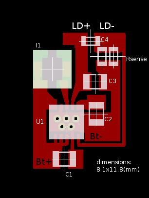
u1= TI
I1= coilcraft LPS3015-222MLB,
C1-3= 10uH ceramic,
C4= low value ceramic,
Rsense= selected using R=0.5/I (where I is the required current).
this driver should not be used without a load.
and LD- must never be connected to Bt-.
power source can be a single AA cell.
