

IgorT
0
- Joined
- Oct 24, 2007
- Messages
- 4,177
- Points
- 0
chimo said:Cool picture time. Here's a shot of my Bluray's beam bouncing around inside my watch crystal.
That IS a very cool picture! Why is it bouncing around like that, and how come the beam is so thin?
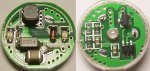
BTW: I'll take some macros tomorrow. The camera i have here sucks at macros for some reason.. Otherwise it would seem these are a little more powerfull from the originals. My BR has a very high Vf after the premature death, and it was still getting 155mA @ 5.35V. The other model gives out 10mA less. And this is with a Ni-MH at 1.33V.
They might just be able to power a red through an AMC.. Quite impressive for such a tiny circuit.


")
