Welcome to Laser Pointer Forums - discuss green laser pointers, blue laser pointers, and all types of lasers

LPF Donation via Stripe | LPF Donation - Other Methods

Links below open in new window

ArcticMyst Security by Avery

Blanking DDL

Joined
Jan 12, 2008
Messages
3,290
Points
83
I'm a little short on the BC337's. But I have quite a few BC237, can I just connect 2-5 in parallel?
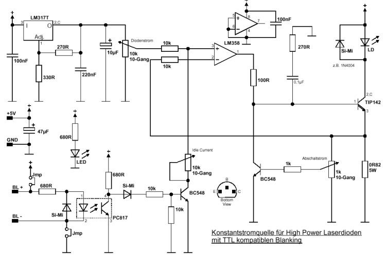


Benm

0
Joined
Aug 16, 2007
Messages
7,896
Points
113
How much current does your laser require?

A bc237 is rated for 100 mA (though it will survive more), so you might need to use more than one with some load balancing resistors. I'd go for the 337 though, its a penny component and quite universal, just stock up on some.
 
Joined
Jan 12, 2008
Messages
3,290
Points
83
I looked through all my scrap circuit boards and found four BC337's. :cool:

But somehow I fail to make this work, here's my circuit:

bc337-1.jpg


The RGB-IC is a LED PWM colour changing board that just goes thought the colour spectrum over and over slowly.

Connected like this both diodes fade up and down together at the same time, instead of slightly overlapping. :(

What did I do wrong? The pulses are around 3-4V, maybe 100Hz.
 

Benm

0
Joined
Aug 16, 2007
Messages
7,896
Points
113
You should connect the outputs from the controller to the base of the transistors, not their emitter. The common + of the controller should be wired to the +12 volts.
 
Joined
Jan 12, 2008
Messages
3,290
Points
83
You mean like this?

bc3372-1.jpg


Sorry it did not work, now it's constantly on whenever the controller is on or off. When I disconnect it from point a. and b. the diode turns off. Also I read 7-8V between point a. and b. :-/
 
Joined
Sep 20, 2008
Messages
17,622
Points
113
Do you have the spec sheet for your "RGB IC" module...
or a part number... or a link to see one.. :-?

Do you have a schematic on how it should be connected to just
LEDS as it was originally designed for... :-?

(I think we are looking at a Negatively switched Open Collector circuit)

Jerry
 
Joined
Jan 12, 2008
Messages
3,290
Points
83
No, I gutted it out from a small "decorative Christmas tree" powered by three button cells. It's a small broad with three LED's and a resistor. The IC itself is just a black epoxy blob on the back. What I've done is replaced the LED's with transistors.

I have found these boards in lots of cheap junk and all are common anode for the LED's.
 
Joined
Sep 20, 2008
Messages
17,622
Points
113
One thing that worries me is that the 3 batteries are only 4.5V...
which would also be the voltage at the +COMMON pin to drive the
LEDs...  and to hook up 12Volts to that pin would not seem to be
prudent....:eek:

Knowing that... I would use Opto-Couplers on the 3 outputs...
The LEDs in the opto-couplers would be connected to the outputs
just as the original LEDs were... then the Transistor output of  the
opto-coupler could run the transistor in your circuit...

This way the 4.5V supply would be isolated from the 12Volt supply... ;)
(you would not need to use pin 6)

Here is a link to a common Opto-Coupler.....

http://www.alldatasheet.com/datasheet-pdf/pdf/2847/MOTOROLA/4N26.html


Jerry
 
Joined
Nov 7, 2008
Messages
5,725
Points
0
Here's a schematic I found of a DDL driver with blanking. It's a bit more complicated than what's being discussed here, but it should offer some insight into how a blanking DDL circuit works..

diodedriverwTTL.jpg


Sorry about the German.. The part labels should all be the same regardless of the language.
 
Joined
Jan 12, 2008
Messages
3,290
Points
83
Hmm I see... Some time ago I made another thread about a similar project and rog8811 suggested opto-couplers too. You can look here if you'd like:
http://www.laserpointerforums.com/forums/YaBB.pl?num=1214844611/0#0

It was something about the opto-couplers that screwed up the signal but I'll give it a shot again. :)
I really need to get me a bread board, *sigh*

Do you mean like this?
bc3373.jpg


I have three CNY17-3's, they should work fine too? http://www.datasheetcatalog.org/datasheet2/1/02zk4u92qu0s3qwufrdfe2ip21fy.pdf


Edit @ ElektroFreak: dang, that is some schematic! I guess Ill have to try that if everything else fails..
 
Joined
Nov 7, 2008
Messages
5,725
Points
0
It looks more complicated than it really is. All you'd need to do to use it is ignore the LM317 circuit at the top left, and just attach any DDL driver output at the 10k pot toward the top left in the schematic just after the LM317 circuit.. That knocks off about a quarter of the circuitry..
 
Joined
Jan 12, 2008
Messages
3,290
Points
83
Hey-hey! The circuit in reply #25 works pretty good! :D

I just had an idea and made another schematic (not tested), does it seem like a good idea?

bc3375-1-1-1.jpg


The same capacitors was used in the schematic in reply #25
 
Joined
Nov 7, 2008
Messages
5,725
Points
0
^The filter capacitors will spoil any hopes of modulation at any decent rate. It would help to use small values, but you lose some of the filtration they provide. Modulation circuitry should be one of the last stages before the laser diode itself, rather than modulating prior to filtering. Capacitors block DC and pass AC, so once you start modulating above a certain frequency, the signal gets sent straight to ground. That's how the capacitors provide filtration. They make sure any spikes get sent to ground rather than to the diode.

If you'll notice on the schematic I posted in reply #24, there are no filter capacitors after the point at which the modulation is fed into the circuit. I know that circuit is a bit more complex, but I only posted it to help give an idea of a good layout..


FireMyLaser said:
Hey-hey! The circuit in reply #25 works pretty good! :D

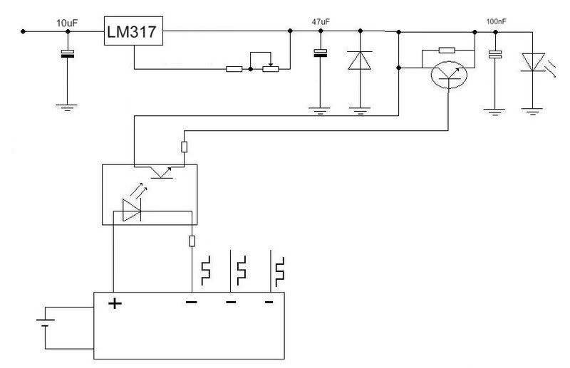
I just has and idea and made another schematic (not tested), does it seem like a good idea?

bc3375-1-1-1.jpg


[highlight]The same capacitors was used in the schematic in reply #25[/highlight]

I'd check again if I were you... the 47uF and 100nF capacitors are not shown in reply #25. They are the problem..
 
Joined
Jan 12, 2008
Messages
3,290
Points
83
So are you suggesting that I should use just one small capacitor on the diode and then a really big capacitor on the power supply?


The same capacitors was used in the schematic in reply #25
What I meant was that I used that circuit and added the capacitors seen in the schematic in reply #27, sorry.
 
Joined
Nov 7, 2008
Messages
5,725
Points
0
One very small tantalum capacitor on the diode is necessary for protection against ESD, the 100nF is good. It's really the 47uF capacitor that is the issue. If I were you , I'd leave it in the circuit and just feed the modulation signal off the emitter of the transistor into the circuit after the protection diode instead of where it is now.. I'm at work so I can't test the circuit, but what I mean is something like this:

BlankingDDL1.jpg


The modulation just needs to come in after the filter caps.
 
Joined
Jan 12, 2008
Messages
3,290
Points
83
I'm having a feeling that the diode might get zapped every time the transistor gets the signal since the LM317 is adjusting the voltage to maintain a constant current? :-/
And the connection between the collector and emitter parallel over the resistor isn't suppose to be there, right?


Top