Welcome to Laser Pointer Forums - discuss green laser pointers, blue laser pointers, and all types of lasers

LPF Donation via Stripe | LPF Donation - Other Methods

Links below open in new window

ArcticMyst Security by Avery

AMC7135 blues. (Gazoo, need your assistance)

chimo

0
Joined
Jun 20, 2007
Messages
650
Points
0
ron said:
Hi Paul,

Tried it. No effect.  :(   Could it be that the IC itself is spoiled? (a bad batch perhaps) Anyway to test?

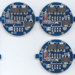
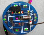
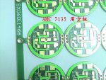
That's certainly a possibility.  If you go back to DX, pick up the model that has a few 7135s per board.  This is a pic of mine - note the poor quality on the one on the top left.  The solder paste has not re-flowed and the components are not properly placed.
 

Attachments

  • DX_7135_small.jpg
    DX_7135_small.jpg
    176.7 KB · Views: 500


ron

0
Joined
Jan 31, 2008
Messages
43
Points
0
Hey Paul,

Sorry was away for sometime. Had to deal with some exams and stuff.

Anyway, I have asked DX to replace my AMCs and they will be sending me a replacement. When I receive it, I will get back to you.

Hey, thanks for all your help man. Will talk to ya later. :)
 

ron

0
Joined
Jan 31, 2008
Messages
43
Points
0
Hey Paul,

Well, I received a new set of AMCs from Dx. They look like the original ones that were on the website photos. Unfortunately, I wired it up, AND IT STILL DOES NOT WORK!!!!!!!!!!!!!!!

AH!!!!!!!!!!!!!!!!

I have attached some photos of my connection. Do you mind telling me if I connected them right?


MAN!!! SO ANNOYED WITH THIS CIRCUIT!!! :mad: :'(
 

Attachments

  • P1010137.JPG
    P1010137.JPG
    69.1 KB · Views: 206

ron

0
Joined
Jan 31, 2008
Messages
43
Points
0
The black wire from the batteries is soldered on to the outer ring, while the red wire is soldered on to the inner ring.
 

Attachments

  • P1010138.JPG
    P1010138.JPG
    43.3 KB · Views: 257

chimo

0
Joined
Jun 20, 2007
Messages
650
Points
0
These boards are different from teh last set. Can you take a nice clear picture of the top? It's hard to see the solder connection at the load wire. Are they the same chips? From what I can see so far it looks OK.
 

ron

0
Joined
Jan 31, 2008
Messages
43
Points
0
Hopefully this picture is good enough for you.


Yup, there are the same AMC 7135 chips. At least I think they are ( i thought DX that I wanted the same replacement, and they gave me these). They look like the ones shown in the picture on their website.


Dude...seriously.... frustrating to be held back from building a laser because of such nonsense. :(

Thanks for your help Paul.
 

Attachments

  • P1010139.JPG
    P1010139.JPG
    67 KB · Views: 228
Joined
Oct 25, 2007
Messages
221
Points
0
Your wiring looks fine in the previous 3 pics. This question might seem dumb but what resistor are you using and have you measured the volts at the output without the resistor?

I was stumped by these boards until I realized that if I made the resistance across the output too low, the board WOULD NOT turn on but would be fine if I turned the resistance on the pot up a little.

Good luck!
 

chimo

0
Joined
Jun 20, 2007
Messages
650
Points
0
You have the wiring correct.

I have been hearing reports of some of the boards at DX and Kai having a very high failure rate.  

On some, the vias are non-functional (they don't connect both sides of the board).  To eliminate that possibility, ttry re-routing the power connectors as shown.  The "or" locations are alternate locations to connect the battery to.  The red "or" connection will by pass the MELF protection diode. Verify the voltages at various points in the circuit. Good luck!

p1010139acx4.jpg
 

ron

0
Joined
Jan 31, 2008
Messages
43
Points
0
Hey, thanks for the input.

Well, I think I used a 5 ohm resistor, just as Paul suggested (I think can confirm that by looking at the first pic to see the colour codes on the resistor).

Ok, guess I will have to try it out on those parts you suggested Paul. When I get the time, I will definitely give it a try.

Tell me, I have a function on my multimeter: it gives a beeping sound when there the positive and negative leads are electrically connected. So any good way to use that to my advantage to test the circuit out? Can I put the positive lead at one point, and the negative lead at another point to see if there is actually a connection?

Again, thanks for the input. :)


Damn these boards.
 

ron

0
Joined
Jan 31, 2008
Messages
43
Points
0
HEY!!!!

WAIT JUST A MINUTE!!!!

I JUST LOOKED AT THE PICTURE THAT I POSTED UP AND REALISED SOMETHING!

ISNT THE DIODE INSTALLED BACKWARDS???!!!?!?!?!
 

chimo

0
Joined
Jun 20, 2007
Messages
650
Points
0
The diode is OK.  The stripe on a diode marks the cathode end.  

The continuity checker on your DMM should show short-circuits. I have attached a photo to show what points should be connected by traces.

If the driver is functioning properly, there should be about a 1.75V drop across the 5 ohm resistor,  around a 2.1V drop across the 7135 and a 0.5-0.7V drop scross the MELF diode.  That's about 600mW across the resistor, so it will get warm.

You should also verify:
1. that your resistor is 5 ohms by measuring it
2. that you are getting about 4.5V from your battery pack (sometimes the cells don't touch the contacts very well)
3. check the continuity between the coloured points I marked. It should read as a short circuit between same coloured dots.
 

Attachments

  • P1010139b.JPG
    P1010139b.JPG
    49 KB · Views: 837
Joined
Oct 25, 2007
Messages
221
Points
0
Nice pic chimo I'm definitely going to save that [smiley=thumbsup.gif] [smiley=thumbsup.gif] [smiley=thumbsup.gif]
 

chimo

0
Joined
Jun 20, 2007
Messages
650
Points
0
I just ran across this pic on CPF.  It shows the traces well (no components on the boards).
 

Attachments

  • amc7135pcb.jpg
    amc7135pcb.jpg
    83.8 KB · Views: 929

IgorT

0
Joined
Oct 24, 2007
Messages
4,177
Points
0
Very nice. And perfect timing... :) Thanks!

I just got a bunch of these (three per board), but noticed odd behaviour.
One of them is sinking 300mA, while two only sink 500mA. Need to do some more testing. Are they usualy more consistent?

EDIT: They all sink 340-350mA if they have enough voltage. It was the batteries fault. It sagged to much.
 
Joined
Sep 1, 2007
Messages
1,591
Points
0
I think he has the postive wire(red) on the wrong pad he has it on the negative. he needs to connect positive right on the positive input. and put the negative were the red wire is thats how i use mine.
 

IgorT

0
Joined
Oct 24, 2007
Messages
4,177
Points
0
Which positive wire are you talking about? The one coming from the battery or the one coming from the resistor onto the round pad?

I keep looking at it, but don't see what you mean. It is connected in a funny way, but it's correct, because of the common positive potential. The current is supposed to flow from the battery through the resistor into the round pad. The resistor is the load here. It's just the colour of the wire between the resistor and the round pad, that is perhaps confusing.


Top