IgorT
0
- Joined
- Oct 24, 2007
- Messages
- 4,177
- Points
- 0
phenol said:the datasheet limits Rin to 500ohms max...
Indeed it does. So what does that mean for this circuit?


phenol said:the datasheet limits Rin to 500ohms max...


my bad :-[phenol said:the datasheet limits Rin to 500ohms max...
So you finished this thing like an hour after we first talked about it?!? Shocked
I'm still shocked. I thought it was just meant as proof of concept (that it fits). So it would just work?!? With the LTC6106?
 it doesn't take much longer to arrange them properly
adgmeijin said:hey woop where did you get the parts of your boost driver? and how do you test the output and current using DMM?
woop said:what current do you need?
adgmeijin said:thanks Igort , actually i set an order for the sample of Dr. Lava's microflex boost driver, i think this may be the solution to make a pen laser with PHR803T LD on it.
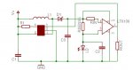
phenol said:ok, suppose Rin=100R and Rout=10k, adjustable. We have a gain of 100. For Rsense=0.1R and Vref=190mV, the min I=1.9mV/0.1=19mA. The max current 6106 is capable of sourcing is 1mA, for 190mV this would be 190R for Rout min. If Rout min is 330R (Resistance of trimmer pot=0 + a fixed 330-R resistor), gain=3.3 and Imax=57.58mV/0.1 = 576mA.
Sounds good.
Transient response and stability have to be verified under all conditions, though.
thats what i was getting at.yes, by using different values for Rmin, Imax could be limited accordingly