Welcome to Laser Pointer Forums - discuss green laser pointers, blue laser pointers, and all types of lasers

LPF Donation via Stripe | LPF Donation - Other Methods

Links below open in new window

ArcticMyst Security by Avery

2-PNP laser driver (easy!)

Benm

0
Joined
Aug 16, 2007
Messages
7,896
Points
113
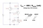
I've drawn out a little circuit i use to drive LD's at constant current, mostly for flashlight-hosted applications.

The circuit should be fairly self-explanatory. Current is set by the sense resistor, that always takes around 0.6 volts. For 200 mA, a 3 ohm resistor would be used, for 300 mA a 2 ohm resistor and such. You can use a variable resistor if you want to. This works fine up to about 500 mA, above which the current ends up a bit lower than calculated.

The 2 PNP transistors arent critical, though the one displayed as BD140 should be able to handle the power you plan on dissipating in your driver. The BD136/138/140 are all capable of 1.2 watts dissipation uncooled or 6 volts drop at 200 mA - fine for the typical setup powering a LD from 2 CR123 cells. You can use any NPN transistor basically, but the ones indicated are commonly available.

Minimal dropout is 0.9 volts, making this driver suitable to run a LD easily off 4 NiMH's as well. Using 3 cells it's a bit tight, depending on the exact diode.
 

Attachments

  • 2pnp.jpg
    2pnp.jpg
    47.2 KB · Views: 6,143


CHP

0
Joined
Sep 30, 2007
Messages
74
Points
8
This is a good circuit; I've used this one and the NPN version before. A capacitor (10's of uF) across the CE of BC557 will create a nice slow soft turn-on of current to the LD. The circuit needs a minimum supply voltage about 0.9 volts above the expected LD voltage. If the supply drops below this voltage the current will be reduced after the BD140 reaches its saturation voltage.

You can also place a variable resistor (~50k) in series with the 1k resistor to reduce the output current but will not regulate the lower current.
 

Benm

0
Joined
Aug 16, 2007
Messages
7,896
Points
113
It's mirror image with NPN transistors works just as well indeed - in case you would use a common-positive LD that's more practical. Adding the extra cap as a slow start works if you need such feature.

Limiting current with a larger resistor in place of the 1k works, but isn't a very good idea. Your current is then bascially limited by the BD140's HFE, which rises with temperature - thermal runaway waiting to happen ;)
 
Joined
Oct 22, 2007
Messages
25
Points
0
Benm said:
The 2 PNP transistors arent critical, though the one displayed as BD140 should be able to handle the power you plan on dissipating in your driver. The BD136/138/140 are all capable of 1.2 watts dissipation uncooled or 6 volts drop at 200 mA - fine for the typical setup powering a LD from 2 CR123 cells. You can use any NPN transistor basically, but the ones indicated are commonly available.

Minimal dropout is 0.9 volts, making this driver suitable to run a LD easily off 4 NiMH's as well. Using 3 cells it's a bit tight, depending on the exact diode.
CHP said:
The circuit needs a minimum supply voltage about 0.9 volts above the expected LD voltage. If the supply drops below this voltage the current will be reduced after the BD140 reaches its saturation voltage.

Am I understanding this correctly that this circuit also can also limit the voltage to that required of the LD ? 6v from 2xcr123 =6vv 4xNiMH 4.8 and 3xNiMH 3.6 (a bit tight) ?

as a normal power diode has a forward Vdrop of about .6 volts and and LD of around 2.8~3.2 volts is this circuit using this idea in other words having say a Vin of any reasonable voltage and and LD .6 or .9 volts below that as long as the current is set correctly will be fine which could mean a blu ray can also be used from 2xcr123 with this circuit ?
 

Benm

0
Joined
Aug 16, 2007
Messages
7,896
Points
113
The circuit is a current source, and will deliver whatever voltage the LD requires for the desired current (up to ca 1 volt below the battery voltage if need be).

You can run a bluray diode from 2 CR123's with this circuit, just select Rsense for the desired current (e.g. for 20 mA, this would be 30 ohms). As I understand blurays take 4 to 4.5 volts at operating current, so with 6.0 volts from the batteries you have plenty of voltage for regulation.
 

CHP

0
Joined
Sep 30, 2007
Messages
74
Points
8
Benm said:
It's mirror image with NPN transistors works just as well indeed - in case you would use a common-positive LD that's more practical. Adding the extra cap as a slow start works if you need such feature.

Limiting current with a larger resistor in place of the 1k works, but isn't a very good idea. Your current is then bascially limited by the BD140's HFE, which rises with temperature - thermal runaway waiting to happen ;)
My point was that you set the max current when the var. resistor was at zero. Then you can back off the current by increasing the var resistor. Even if the current varies with beta(temp), the max current has already been set. It is an easy way to use a low power (i.e. small) potentiometer to back off the current. The low power setting is useful when trying to get the best focus on a spot without being "blinded" by the high power beam.
 

danq

0
Joined
Sep 18, 2007
Messages
835
Points
18
Yes, this works very well - I'm using the NPN version with my blu-rays behind a Photon micro-light pwm controller. With the litte power draw of the gb diode I was able to get away with surface mount components. The power across the output transistor is reduced by using a low-saturation-voltage unit - mine's a FSB560A, drops only 0.3V and can take 1/2 watt in theory... 1/2 watt at .3V means 1.6 Amps! in a package just about too small for me to see without my glasses :eek:
 

Benm

0
Joined
Aug 16, 2007
Messages
7,896
Points
113
Even if the current varies with beta(temp), the max current has already been set. It is an easy way to use a low power (i.e. small) potentiometer to back off the current. The low power setting is useful when trying to get the best focus on a spot without being "blinded" by the high power beam.

Very true - i just dont want to encourage anyone relying on regulation like that. But as long as your define the maximum by chosing Rsense correctly that provides a safe ceiling to the current.

The power across the output transistor is reduced by using a low-saturation-voltage unit - mine's a FSB560A, drops only 0.3V and can take 1/2 watt in theory... 1/2 watt at .3V means 1.6 Amps!

Using a low Vsat transistor lowers the voltage drop required, but will not lower the power dissipated in typical operation. Remember that all the excess voltage will be dissipated in the transistor, so it always burns the current multiplied by the difference between battery and LD voltage.
 
Joined
Oct 22, 2007
Messages
25
Points
0
so in referring to my earlier post I can use this circuit with my LD using say 8v4 in and a LD needing 2v8~3v2 as apposed to ddl's circuit witch gives a Vout-3Volts of the input I am still lost in new technology but want to learn more or keep up to date at least

I understand v=I/R I=VxR and R=I/V

technology now to me is like comparing a Pentium 1 to the latest processor
 

Benm

0
Joined
Aug 16, 2007
Messages
7,896
Points
113
This does basicall the same DDL's circuit does: limit the current to the LD regardless of input voltage, as long as the voltage is sufficient.

The main difference is that this circuit works with a minimum of 1 volt difference, where the LM317 needs 3 + 1.25 = 4.25 v excess voltage to work reliably.
 

danq

0
Joined
Sep 18, 2007
Messages
835
Points
18
Benm said:
Using a low Vsat transistor lowers the voltage drop required, but will not lower the power dissipated in typical operation. Remember that all the excess voltage will be dissipated in the transistor, so it always burns the current multiplied by the difference between battery and LD voltage.
but there's also a resistor in series there - whose resistance doesn't vary (nominally).

So with input of 6V, at 40mA current, the dissipations are:

LDv=4.5 LDi=.040 LDp=.180W
Qv=0.3 Qi=.040 Qp=.012W
Rv=1.2 Ri=.040 Rp=.048W (30 ohms)

and for a 2.5V LD at 300mA, with 3V input:

LDv=2.5 LDi=.300 LDp=.750W
Qv=0.3 Qi=.300 Qp=.090W
Rv=0.2 Ri=.300 Rp=.060W (.67 ohm)

So it looks like the low Vsat transistor could be used to drive a group-buy red - on a 3V battery - and the components still have power rating to burn?
:-?
somebody please check my math...
 
Joined
Aug 15, 2007
Messages
790
Points
0
@.3A the GB diode will Prob. have more like a 2.88V forward drop. But I've seen 2 harvested diodes that could burn at just 2.5-2.6V and around .16A
 

Benm

0
Joined
Aug 16, 2007
Messages
7,896
Points
113
danq said:
but there's also a resistor in series there - whose resistance doesn't vary (nominally).

So with input of 6V, at 40mA current, the dissipations are:

LDv=4.5  LDi=.040  LDp=.180W
Qv=0.3  Qi=.040 Qp=.012W
Rv=1.2  Ri=.040  Rp=.048W (30 ohms)

and for a 2.5V LD at 300mA, with 3V input:

LDv=2.5  LDi=.300  LDp=.750W
Qv=0.3   Qi=.300    Qp=.090W
Rv=0.2   Ri=.300     Rp=.060W (.67 ohm)

So it looks like the low Vsat transistor could be used to drive a group-buy red - on a 3V battery - and the components still have power rating to burn?
:-?
somebody please check my math...

The resistor also dissipates some of the power indeed. The voltage across it is a constant 0.6 volts regardless of current chosen. So at 6V input on a red LD the distribution would be something like:

0.6 volts over the resistor
2.6 volts over the transistor (varies with actual battery voltage)
2.8 volts over the laser diode (realistic value around 200 mA).

Driving the 16x sony LD will not work from 3 volts at 200 mA or so, as it takes 2.8 volts on its own.
 

danq

0
Joined
Sep 18, 2007
Messages
835
Points
18
Benm said:
The resistor also dissipates some of the power indeed. The voltage across it is a constant 0.6 volts regardless of current chosen. So at 6V input on a red LD the distribution would be something like:

0.6 volts over the resistor
2.6 volts over the transistor (varies with actual battery voltage)
2.8 volts over the laser diode (realistic value around 200 mA).
:-[ Right - I thought I was forgetting something, and that something is why the circuit works: we're regulating the voltage across that resistor, using the varying effective resistance of the transistor - duh! thanks, Benm.
my arithmetic is ok, but my logic board has a loose connection this morning ::)

So that's over 1/2 watt in the transistor, slightly outside its specs - good thing I didn't try that with my little board. then again, semiconductors are dirt cheap these days...
:) DanQ
 
Joined
Aug 15, 2007
Messages
790
Points
0
Somebody send DanQ some coffee tomorrow morning ;)
Coffee is the solder that holds the components of MY logic board together.
 

wall

0
Joined
Aug 1, 2011
Messages
55
Points
0
Sorry for reviving an old thread, but this is the only driver I could find to power a case-negative diode from a single li-ion.
Are there other transistors I could use instead to achieve a lower dropout?


Top