Welcome to Laser Pointer Forums - discuss green laser pointers, blue laser pointers, and all types of lasers

LPF Donation via Stripe | LPF Donation - Other Methods

Links below open in new window

ArcticMyst Security by Avery

635 Wiring in Host

bobo99

0
Joined
May 18, 2011
Messages
128
Points
18
Hey Guys,

I picked up a diode and flexdrive soldered together from DTR - https://sites.google.com/site/dtrlpf/home/diodes/mitsubishi-635nm-300mw-diodes

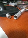
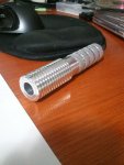
And got Ehgemus to build me a host. (1x18650)

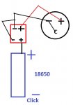
The host is bored out completely, so the positive flex battery lead will get an isolated spring to make contact with the battery, however I am at a loss as to how to connect the negative battery lead to the flex drive...

Suggestions are appreciated.

Edit: I'm reading that I could in theory attach flexdrive negative battery to diode case pin... however the case pin is already bridged with the negative diode... so time to get the soldering iron out ?
 

Attachments

  • IMG_20120110_214224.jpg
    IMG_20120110_214224.jpg
    50.5 KB · Views: 198
  • IMG_20120110_214210.jpg
    IMG_20120110_214210.jpg
    51.7 KB · Views: 211
Last edited:


Joined
Mar 22, 2011
Messages
791
Points
0
If the case pin is set up so the diode is Case negative, you don't need to attach the driver's ground input pad to the negative pole of the battery. The FlexDrive uses a common ground aka you can use the diode to supply the ground.
 

bobo99

0
Joined
May 18, 2011
Messages
128
Points
18
Ok so just to clarify... Since the case pin is bridged with negative, I can do whats in my picture, and the circuit will be completed, because the diode is set to case negative.

Conversely I could bridge the case pin- with the diode positive, and flip battery upside down, and make the battery -> flexdrive negative contact and that would work as well ? Making a "case positive" host?

So the case pin is just used, if its difficult to completed the circuit?
 

Attachments

  • Untitled.jpg
    Untitled.jpg
    30.4 KB · Views: 201

DTR

0
Joined
Jun 24, 2010
Messages
5,684
Points
113
Yes you can just clip the negative wire coming out of my module. This will be a one wire installation. Just solder that to the wire Ehgemus has coming out of the host and set your module in with the set screw. There could not be a simpler build.;)

Awesome host by the way.:beer:
 

bobo99

0
Joined
May 18, 2011
Messages
128
Points
18
Thanks, the host looks even better in person! Will get pics out soon!

"Just solder that to the wire Ehgemus has coming out of the host"

I'd love to, but there is no wire coming out of the host :)

Its a host - straight through, and a clicky at the end.

However if the picture I posted will work, then that's what it'll be. Just solder negative-flex-battery-lead onto the case pin and add a spring then! :)
 
Last edited:

DTR

0
Joined
Jun 24, 2010
Messages
5,684
Points
113
Well what you could do is cut a circular piece of plastic and glue it to the bottom of the module I sent to isolate a spring on it. Then put a small hole in the plastic for the red positive wire to come through. Get a spring and solder the positive to it then tuck the slack wire back in the module and glue the spring on the plastic to make contact with the positive connection on the battery. The only problem I see is getting the spacing right so the module is flush with the front and the battery fits snug. If this makes any sense.:p

Oh and yes your diagram is correct but you don't need to worry about running the black wire back to the case pin as my modules are already case negative. As I bridge the case pin and the negative pin before attaching the Flexdrive. You can just clip the lead.;)
 
Last edited:

bobo99

0
Joined
May 18, 2011
Messages
128
Points
18
Crystal clear :)

Thats actually a better idea, as Im having trouble finding insulated springs!

Thanks DTR and Fretwecker94!


Top