Welcome to Laser Pointer Forums - discuss green laser pointers, blue laser pointers, and all types of lasers

LPF Donation via Stripe | LPF Donation - Other Methods

Links below open in new window

ArcticMyst Security by Avery

Kenometer laser power meter interest. LITE version *closed*

Kenom

0
Joined
May 4, 2007
Messages
5,629
Points
63
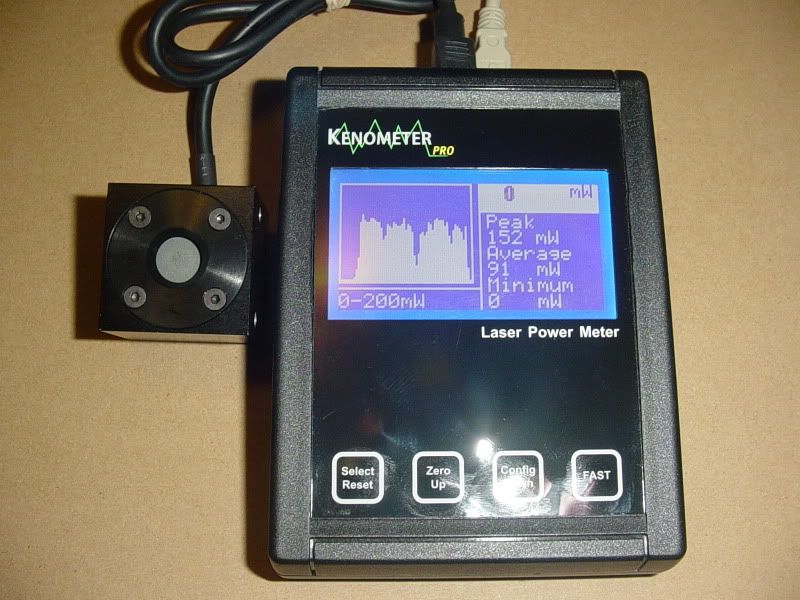
mario you should post the pictures of the ripple coming from the dc/dc converter tests.

As to the ripple coming from the output, it's still not a bad idea to use the capacitors you mentioned. Heck i've never heard of having too much filtering.. LOL
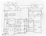
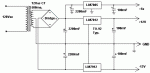


Joined
Jul 27, 2007
Messages
3,642
Points
63
Haha yeah, it's pretty terrible - I don't know how they could make some of these so bad....

Each square on the scope screen represents 20mV

Spikes in relation to the switching frequency
scope2.JPG


Inductive ringing on this one
scope3.JPG


wat
scope1.JPG


Edit - the reflections of the confederate flag is my roommate's decoration in case anyone was wondering...
 

SHIN

0
Joined
Jul 25, 2009
Messages
207
Points
18
My kenometer lite was fixed as Kenom suggested.
Couple of 100uF electrolytic caps were added at the cables between thermopile and DC/DC converters.
But I can't do anything further because black "hot glue" is covered the parts and cables so I can't even differenciate them.
After the fix, the fluctuation of the reading was somewhat lessened, but not clearly.

I have a question:
Is it dangerous that using my kenometer lite (fix of two 100uF caps) without further fixation (Mario's circuit)?

If there is a big problem with using "as it is", I'd like to get the circuit board and parts except thermopile and LED panel? I can pay for that..

SHIN
 

Kenom

0
Joined
May 4, 2007
Messages
5,629
Points
63
no shin as long as you use teh caps on teh output, you will be fine. You might want to increase the value of the capacitors as laserbee recommends tho.
 

HIMNL9

0
Joined
May 26, 2009
Messages
5,318
Points
0
some dc-dc converters are bad beasts, about ripples ..... just as suggestion, place some 100nf or 220nf ceramic capacitors in parallel to all the electrolitics ones (electrolitic capacitors are not very efficent against high frequency spikes, due to their internal reactance, so ceramic ones in parallel helps a lot, sometimes)

The better combination can be: 100/220uF standard + 1/2,2 uF tantalium + 100/220 nF ceramic in parallel ..... capacitors have not a high cost, after all :) ..... also, using some counter-wired bobines or C-L-C pi-greek filters can help too ..... like the one that you already have placed on the output of the head ..... if you have occasion, try to complete it (adding another capacitor also from output and GND, and paralleling them with 100nF ceramic ones) ..... same thing for the one on the dc-dc inputs, and usinf the same on the dc-dc outputs, you probably end taking away 90% or more of these spikes .....


EDIT: sorry, i just had another idea ..... ground loops also, sometimes, contribute to link ripples and spikes where you don't want them ..... decouple the inputs and outputs of the dc-dc converters, coupling the grounds only on the signal side, and place a RF trap on the inputs of the converters ..... something like this, at the end:

attachment.php


Sorry for the bad drawing, i just sketched it on-the-fly :p ..... and, also, use good size wires (i know that there's no high currents in the circuit, but is always a good thing to use wires of a decent size for wire-up power sections, like, 0,5mm dia, at least, especially for the input of the dc-dc converters)
 

Attachments

  • powerlb01.jpg
    powerlb01.jpg
    124.3 KB · Views: 343
Last edited:
Joined
Jul 27, 2007
Messages
3,642
Points
63
Damn, that would add a lot of cost and complexity - Once the power input to the head is cleaned up it will not require an additional filter on the output. I originally only had the one on the output to save component costs but it's not really ideal since the head amp is still being fed with a dirty signal.

My design just uses single low-esr capacitors in the pi filter.

Filtering2.1.PNG
 
Joined
Sep 20, 2008
Messages
17,622
Points
113
Well that's not the same drawing at all MM...:yh:

Filtering2.1.PNG


This one makes more sense... :cool:
I would... however... change the capacitor voltages to at least 25V
since there is 12VDC out of my DC/DC converters..
10V caps won't do...

As I stated above...
It is the Output of the DC/DC converters that cause
the Ripple... that is not addressed on Kenom's posted Drawing...

When working with using MCUs and/or sensitive Op Amp circuits
that require a Split Supply (+12 -12 & +5) we prefer using a triple
regulated Split Supply circuit like this one... There is virtually no
60Hz ripple and absolutely no High Frequency Ripple from boost
converters on its output and uses few parts....

26388d1270672528-kenometer-laser-power-meter-interest-lite-version-closed-split-supply-mcu.gif


Jerry
 

Attachments

  • Split Supply MCU.gif
    Split Supply MCU.gif
    4.6 KB · Views: 242
Last edited:
Joined
Jul 27, 2007
Messages
3,642
Points
63
Yes, and I was using a linear regulated +/-12vdc Lambda PSU when I was building the prototype of the Kenometer Pro series. That is why the problems didn't appear until later. It worked fine for the prototype but wouldn't allow the meter to be portable and run off batteries and USB.

I did more testing today and found my second drawing to actually work significantly worse than the original. :(

These converters also emit a strong enough EMF that nearby wires were having noise inducted into them, enough to cause fluctuations on the mcu and visible spikes on my oscilloscope.

I have since removed the circuitry and reverted to my original design. Once again the power is smooth and free from any visible ripple on my scope. I have instructed Kenom to do the same. The ground for the thermopile was also soldered directly to the MCU board instead of the converter stack. This eliminated the small voltage difference created in the inductor.
 

Kenom

0
Joined
May 4, 2007
Messages
5,629
Points
63
I tell ya. This is one huge headache. As long as I use big psu's or something along those lines, I can get a nice stable output from the thermopile, but input a dc/dc converter into the mix and literally all hell breaks loose.

Things was using a computer psu. I was using a converter and mario the psu as well so they couldn't see the issues I was having until I shipped him some of teh dc/dc converters I was using and it was like christmas and comprehension lit up... LOL

If anyone can find a dc/dc converter with 2 outputs both -/+ 9 to 12vdc at 80ma to 200ma, that has no noise whatsoever, I would love them forever.

If anyone would like to switch over to a cheap psu that provides both of the required outputs for both the panel meter and the thermopile. You can get one here.
http://www.mpja.com/prodinfo.asp?number=15871+PS

However if you do go to that psu, the offset circuit for the zero will not work as the ground for the 12v are not isolated which is required.
 
Last edited:
Joined
Sep 20, 2008
Messages
17,622
Points
113
Yes, and I was using a linear regulated +/-12vdc Lambda PSU when I was building the prototype of the Kenometer Pro series. That is why the problems didn't appear until later. It worked fine for the prototype but wouldn't allow the meter to be portable and run off batteries and USB.

I did more testing today and found my second drawing to actually work significantly worse than the original. :(

These converters also emit a strong enough EMF that nearby wires were having noise inducted into them, enough to cause fluctuations on the mcu and visible spikes on my oscilloscope.

I have since removed the circuitry and reverted to my original design. Once again the power is smooth and free from any visible ripple on my scope. I have instructed Kenom to do the same. The ground for the thermopile was also soldered directly to the MCU board instead of the converter stack. This eliminated the small voltage difference created in the inductor.

Yeah... I've seen some weird problems as well on some of my
circuits that were caused by ground loops... that were solved by
taking all the grounds to a central tie point..

Jerry
 
Joined
Sep 20, 2008
Messages
17,622
Points
113
I tell ya. This is one huge headache. As long as I use big psu's or something along those lines, I can get a nice stable output from the thermopile, but input a dc/dc converter into the mix and literally all hell breaks loose.

Things was using a computer psu. I was using a converter and mario the psu as well so they couldn't see the issues I was having until I shipped him some of teh dc/dc converters I was using and it was like christmas and comprehension lit up... LOL

If anyone can find a dc/dc converter with 2 outputs both -/+ 9 to 12vdc at 80ma to 200ma, that has no noise whatsoever, I would love them forever.

If anyone would like to switch over to a cheap psu that provides both of the required outputs for both the panel meter and the thermopile. You can get one here.
5.1V, 2A and +-12V, 200mA ARTESYN POWER SUPPLY-MPJA, Inc.

However if you do go to that psu, the offset circuit for the zero will not work as the ground for the 12v are not isolated which is required.

If you want to get rid of any PS ripple problems you need to get
away from Switching Power Supplies... IMO
Been there... done that... and spent a lot of $$$$ learning that...

The Item you linked to looks like a SPS...
I would put the loaded output of that linked PS on the scope
before I would suggest using it... But that's just me...

We won't put anything on the market until I'm satisfied it won't
come back and bite me on the A$$....
Like I said... been there... done that..:beer:

Jerry
 

Kenom

0
Joined
May 4, 2007
Messages
5,629
Points
63
This is kinda off topic and not related to these particular meters but we do have a few that are monitoring this thread to look for updates on teh Kenometer pro's.

So without further ado.

053a8847.jpg

5cc9c32f.jpg

fc3e019d.jpg

cbf6781a.jpg

a56a68f8.jpg

b8959a49.jpg

4dbe180c.jpg

c90662d7.jpg

852bd4b5.jpg

3834fac8.jpg

b8395e8e.jpg

DSC00085.jpg
 

HIMNL9

0
Joined
May 26, 2009
Messages
5,318
Points
0
I tell ya. This is one huge headache. As long as I use big psu's or something along those lines, I can get a nice stable output from the thermopile, but input a dc/dc converter into the mix and literally all hell breaks loose.

Uhm, have you checked the TOTAL current that is required from the reading head, when it's hooked on the circuit and working ?

I'm asking you, cause i already had problems with dc-dc converters in this field, with numerous prototypes ..... as example, i made a video switcher distributor with a chip that was stated +/-12V 50mA, and used a +/-12V 100mA dc-dc converter, thinking that the double was enough (as anyone can imagine :p) ..... and it ended with the IC that had that absorption only without input signals, rising to 80mA with the signals applied, and the 100mA dc-dc converter was messing up all with ripples and spikes (ofcourse :p), until i've substituted it with a 250mA converter .....

Also, keep in mind that these dc-dc converters are working usually around 100KHz or more, and also if they use a toroidal transformer, are not shielded ..... in some very delicate situations, placing them one near the other can induce some parasitic coupling between the 2 inductors, messing up with the regulation circuits ..... is always a good thing to keep them distant at least 2 or 3 centimeters ..... (but i don't think that this can be the main problem, for your application)
 
Joined
Sep 20, 2008
Messages
17,622
Points
113
I've checked the current on the small heads and it is aprox. 10-12mA per
side to ground... was difficult to get a good reading with the ripple problem
pulling more on one side of the split supply than the other before I found
the fix.

Jerry


Top