

- Joined
- Feb 5, 2008
- Messages
- 6,252
- Points
- 83
Hey guys,
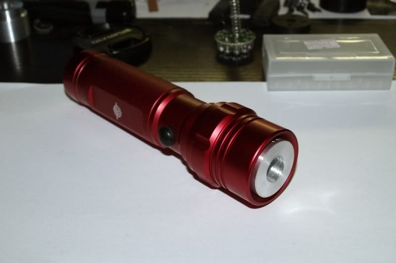
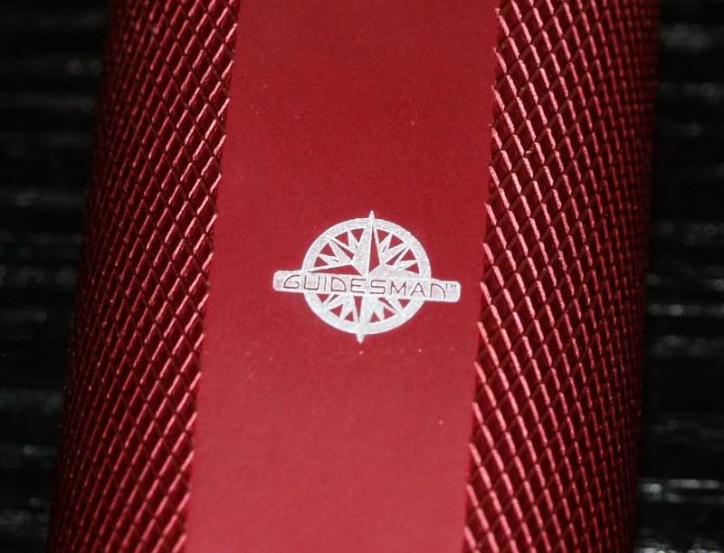
so there is this host which people say it's like original Guidesman, with logo and all:
Red:
eBay - New & used electronics, cars, apparel, collectibles, sporting goods & more at low prices
Gray:
http://www.ebay.com/itm/14LED-Flash...lashlights&hash=item3cb99bb8b7#ht_2412wt_1163
So here it is!
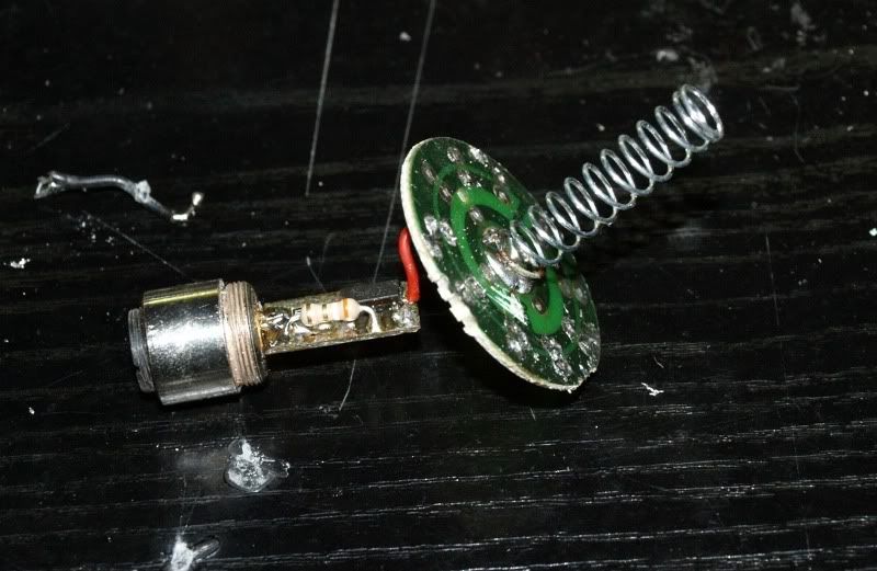
The heatsink itself looks like this:
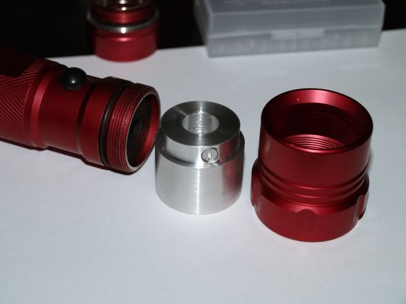
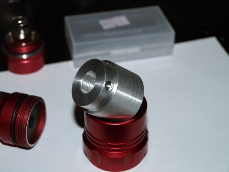
There is a set screw to hold your Aixiz or other laser module in the tinner part, obviously.
The heatsink's lenght is enough to support against the body even if you do not use the board that comes with the light (one containing all the LEDs, you can get rid of them and use it as contact board with it's long spring), but you can also use the board if you want.
There is enough room behind the Aixiz for a variety of drivers which you can attach to the diode directly (like Flex or MicroBoost or any DIY driver).
It is reccomendable that you give a little sandpaper to the edge of the body pressing against the heatsink here:
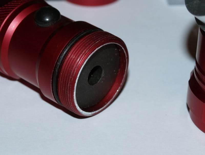
...for better electrical contact.
That's it folks, direct pressfit version possibly on the way, maybe even have a socket for 17mm driver boards for DX drivers in it, but more on that later.
Heatsinks are $18 a piece, free shipping worldwide - as always.
Enjoy")
P.S. Any feedback is welcome!
EDIT - More info about using the PCB as contact board.
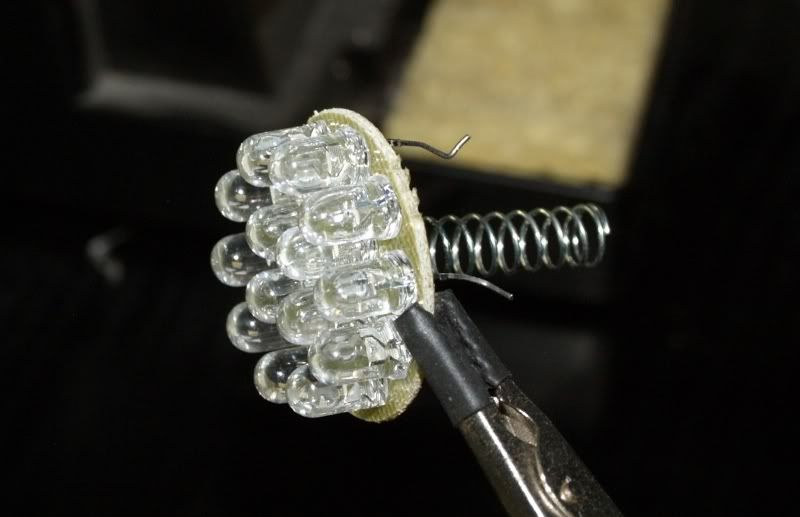
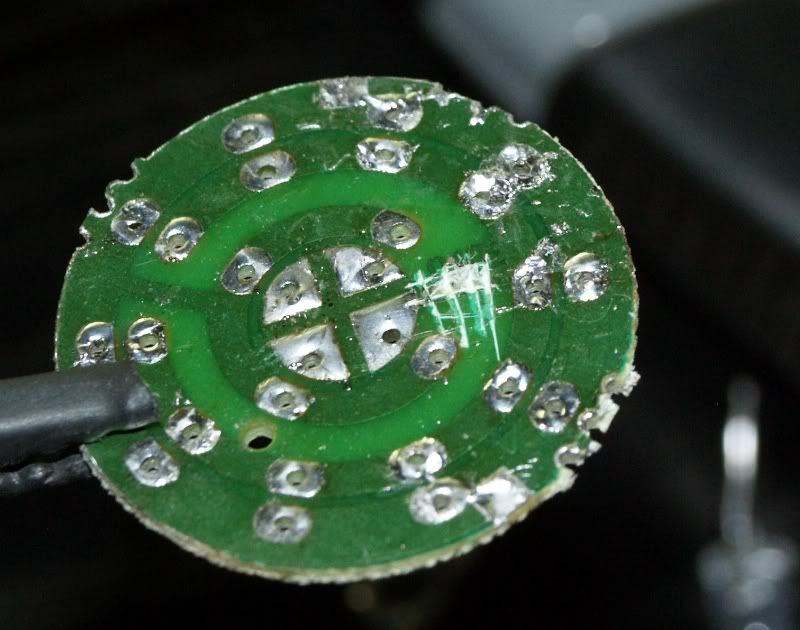
That's the board with all the LEDs on it. Remove the black spacer ring.
Obviously, get rid of everything, including the spring (for the moment):
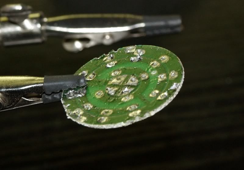
Now, you need to cut this trace here, to prevent the battery + connection shorting against the ground (heatsink and host):
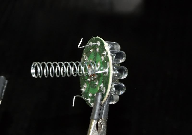
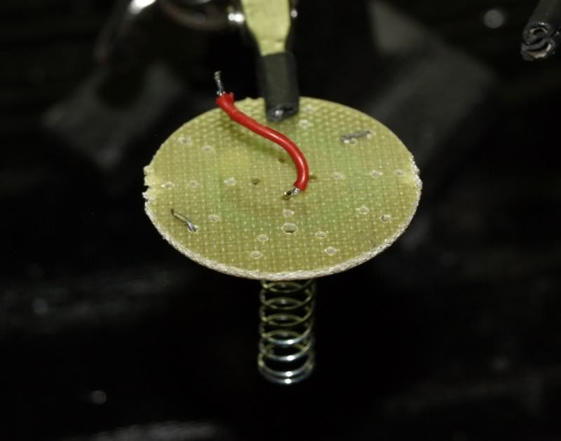
Next, use a couple of those long diode pins to form a connection between heatsink and host (if you don't do this, your heatsink will remain electrically insulated from the rest of the host). Leave the pins sticking out on the heatsink side, solder them on the host contact side on the outter most ring on PCB.
Add your stuff and you're done!
Just put everything back together the way you took it apart, pretty straight forward.
Note, if you do not use the PCB, heatsink is long enough to make the electrical connection to the host itself, but you need to desolder the long spring from the PCB and add it to your driver to form a connection to the switch.
so there is this host which people say it's like original Guidesman, with logo and all:
Red:
eBay - New & used electronics, cars, apparel, collectibles, sporting goods & more at low prices
Gray:
http://www.ebay.com/itm/14LED-Flash...lashlights&hash=item3cb99bb8b7#ht_2412wt_1163
So here it is!
The heatsink itself looks like this:
There is a set screw to hold your Aixiz or other laser module in the tinner part, obviously.
The heatsink's lenght is enough to support against the body even if you do not use the board that comes with the light (one containing all the LEDs, you can get rid of them and use it as contact board with it's long spring), but you can also use the board if you want.
There is enough room behind the Aixiz for a variety of drivers which you can attach to the diode directly (like Flex or MicroBoost or any DIY driver).
It is reccomendable that you give a little sandpaper to the edge of the body pressing against the heatsink here:
...for better electrical contact.
That's it folks, direct pressfit version possibly on the way, maybe even have a socket for 17mm driver boards for DX drivers in it, but more on that later.
Heatsinks are $18 a piece, free shipping worldwide - as always.
Enjoy
P.S. Any feedback is welcome!
EDIT - More info about using the PCB as contact board.
That's the board with all the LEDs on it. Remove the black spacer ring.
Obviously, get rid of everything, including the spring (for the moment):
Now, you need to cut this trace here, to prevent the battery + connection shorting against the ground (heatsink and host):
Next, use a couple of those long diode pins to form a connection between heatsink and host (if you don't do this, your heatsink will remain electrically insulated from the rest of the host). Leave the pins sticking out on the heatsink side, solder them on the host contact side on the outter most ring on PCB.
Add your stuff and you're done!
Just put everything back together the way you took it apart, pretty straight forward.
Note, if you do not use the PCB, heatsink is long enough to make the electrical connection to the host itself, but you need to desolder the long spring from the PCB and add it to your driver to form a connection to the switch.
Last edited:


