Welcome to Laser Pointer Forums - discuss green laser pointers, blue laser pointers, and all types of lasers

LPF Donation via Stripe | LPF Donation - Other Methods

Links below open in new window

ArcticMyst Security by Avery

8X Diode Murder fund

daguin

0
Joined
Mar 29, 2008
Messages
15,989
Points
113
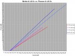
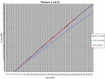
Looks like we have our first murder candidate plotted. The other two are installed in modules too, but i haven't touched them yet...
So far i will only say, that the Vf tracked with the Pioneer diode almost spot-on, while the efficiency was clearly quite a bit lower than the first 203BK i've tested.
But the results are consistent with what i've seen elsewhere on the forum when it came to LG 8x's....

And so it begins . . . . .:evil:

Peace,
dave


Krutz

0
Joined
Nov 21, 2007
Messages
1,733
Points
48
its beginning, great! :)
interesting, the forward voltage flattens out.. perhaps we could see some kind of limit by observing the voltage, how far to go maximum? just guessing here!

manuel
 

IgorT

0
Joined
Oct 24, 2007
Messages
4,177
Points
0
its beginning, great! :)
interesting, the forward voltage flattens out.. perhaps we could see some kind of limit by observing the voltage, how far to go maximum? just guessing here!

manuel

It never really flattens out, but it is true, that smaller and smaller increases in voltage are needed to achieve the same increase in current...

Sometimes (towards the end) the difference between 10mA is as little as ~0.01V (that's the resolution of my Diode Analyzer)..

But it would be physically impossible for it to become flat-flat, if you know what i mean.

I don't know if this means anything or not.. And it also has a lot to do with heat.. I don't have constant temperature for the plotting yet. And Vf drops as the temperature goes up... The testing setup was actually my v3 heatsink/module in a laser body - no extra heatsinking (and yet the Po line remained straight)!

The power should have curved down a bit as well, but it's not really noticable in the graph.. However if i were to set this laser to 360mA and run it cold, it would have ~465mW instead of the 458mW where it peaked in the plot... So i guess this curving due to heat is so gentle and slow that we don't really see it..

There was a moment where my Diode Analyzer suddenly shut down! One of the Li-Ions powering it went into underdischarge protection! I had to replace it. During this time the laser cooled off, and when i turned the Analyzer back ON again, surprisingly the power line continued straight, but the temperature difference produced a slightly noticable "jump" in the Vf line... :angel:


Another thing i wanted to say... The "slightly" lower efficiency of the first LG 8x i tested, compared to the first Pioneer 8x i tested worried me a little at first.

So i made another plot. This time comparing 8x diodes to 6x diodes, or rather A 6x diode and a 100mW CW Nichia (which seeems to be the same thing +/- a few mW in rating - identical to high efficiency GGWs)...


This plot now shows four diodes:
- the two blue(ish) ones are 8x's
- the two red(ish) ones are 6x's...

The red one is my first personal 6x out of a GGW drive, which cost me about $300 to obtain! After going through almost 70 reject GGW sleds, i now classify a GGW with such an efficiency as a "normal" GGW diode...

The 100mW Nichia just had a higher efficiency, but there are GGWs, that match it or even exceed it... I call those "high efficiency" or "freaks"...


The reason i'm showing this plot is this..
I believe that the LG 8x is a "normal" efficiency 8x diode...
The Pioneer 8x i used to make FrancoRob's laser just happened to be a higher efficiency one!

But the angle between the two 8x's is no different than the angle between a normal and a high efficiency 6x...
And that is good! Because i know that my "normal" efficiency 6x diode lasted a year of extreme abuse!

It was often ON for 30 or even 60 minutes at once, just to record a power stability graph, it was once even forgotten ON till the battery went flat (3 hours)!

I never used any kind of duty cycle with it, and towards the end i even had to raise the current for it to finally die!


My point is, that this LG 8x i tested last night is not a low efficiency diode. It's most likelly a normal or average efficiency one. As i already explained in an earlier post, i don't believe the manufacturers use low efficiency diodes for drives - it simply wouldn't work (every low efficiency GGW i test dies rapidly!)...

It's possible we will find slightly lower efficiency ones among the next 12 i'll test, some small variations are to be expected, some might stand out a little more than others, but i don't expect any REALLY BAD diodes.


If i had to guess, i'd say the rest of the plots will likelly be within the two blue lines already on this graph. But there could be exceptions. And if such an exception goes below the lower blue line, it will be our designated murder-candidate... :evil:

It's just natural selection folks... :angel:


P.S. And before someone asks, the 8x's were tested with the 405-G-1 lens, the 6x and Nichia were tested with an AixiZ acrylic (it was a long time ago)...

But this doesn't matter in this case, because all i was interested in was the DIFFERENCE between the SLOPE ANGLES!
If the 6x and the Nichia were given a short FL AR coated lens, their two lines would probably almost overlap the two blue lines.... I just did this plot to compare a normal diode to a high efficiency diode for both 6x's and 8x's...

Now i feel much more confident that we won't find weakling diodes in drives...
 

Attachments

  • 6x's vs 8x's - Comparison PIV Plot - LR.JPG
    6x's vs 8x's - Comparison PIV Plot - LR.JPG
    209.3 KB · Views: 123
Last edited:

IgorT

0
Joined
Oct 24, 2007
Messages
4,177
Points
0
I tested the second diode last night and as predicted it remained between the two lines... :yh:

I will test the third (and last for now until the mini-GB diodes get here), type in the numbers and make the plots of the first three, but unfortunatelly first there is some IMPORTANT work i have to finish...
 

daguin

0
Joined
Mar 29, 2008
Messages
15,989
Points
113
. . . but unfortunatelly first there is some IMPORTANT work i have to finish...

I can write you a note, excusing you from the work, if you need it Igor :angel:

Dear Igor's customer,

Please excuse Igor from doing work for you today. He is busy making >8,000 people happy

Signed,

One of the expectant ones.


There! That should get you out of it . . . . .

You're welcome :san:

Peace,
dave
 

IgorT

0
Joined
Oct 24, 2007
Messages
4,177
Points
0
EDIT: OK, OK, i took a break and typed in the numbers for the second LG 8x diode, and added it to the comparison plot with the first LG diode and FrancoRob's Pioneer 8x...
I showed this plot before, with only the Pioneer 203BK and the first LG 8x Dave sent me. Originaly that diode - now designated LG 8x #01 - was intended for Dave's 8x build with my host and driver...

With the second one i again went very far, because i also wanted to confirm Arenared's results from another thread (he claimed 545mW from an LG 8x at 360mA, which seemed odd to me from slope efficiency calculations)..
Since the 203BK diode i used in Franco's build seemed to be a VERY HIGH efficiency one, i put it on the plot, just to have something to compare LG's to (and ultimatelly to see if they are similar or even the same as diodes used in the Pioneer drives - as predicted by Dave).

Well, the diode now designated as LG 8x #02 surprised me with it's efficiency, which turned out to be pretty much identical to the first 8x diode i ever handled - the Pioneer.. As you can see, the two lines practically overlap! Here and there the LG 8x #02 line (dark blue) peaks out from behind the 203BK line (red)..


With FrancoRob's diode i was very worried, didn't want to risk a thing, wanted to make sure his expensive diode would live a long and happy life, so as soon as i reached >410mW @ 290mA i simply stopped, took a photo of the testing setup, typed the numbers in and finished the laser (oh, and started breathing again! :yabbem:)...

But here we are murdering 8x diodes right? And we know some are surviving at powers above 500mW (even if we don't know for how long, besides people are now setting them to 360mA almost by default). So i thought a quick plot to 360mA couldn't hurt, right? Besides, i went to 360mA with the first LG #1 as well... :evil:

360mA was where i set the Imax on my Diode Analyzer before the test (so i couldn't overshoot by accident)..
So i continued in short steps till i reached this preset limit....

At 360mA the LG 8x #2 did 518mW!

If i were to convert it into a laser, set to this same current, and turned it ON cold, the power would probably be 522-525mW, here the power was lowered slightly, by the fact that the diode and it's heatsink warmed up during plotting...

When i got to 360mA, i quickly looked at the LPM and the Vf reading on the analyzer, memorized them, and turned the current down as fast as i could, because i really didn't want to strain the diode - not even for long enough to type in two numbers (i really don't think such high currents are good for them)!

So, here is the resulting comparison PI plot. I have full PIV data for each diode stored separatelly of course...


Conclusions so far:
- It seems there is some consistency in diodes from drives. Definitelly MUCH more than with reject sleds (but there could still be 11 surprises waiting)!
- It is very likelly that the Pioneer and LG use the SAME diode for 8x drives. The efficiency was identical and the Vf of LG #2 tracked with the Pioneer almost spot on (minor variations are always present).
- The diode Dave originally wanted to have converted into a laser is likelly gonna get murdered in the end, unless TWO of the next 11 happen to have an efficiency lower than LG #01 (unlikelly but possible)!
- Arenared's best out of three LG 8x's is either a super-freak or his LPM is showing 5-7% more than mine (LG #2 @360mA would measure in at 554mW on Scopeguy's LPM for example - the surpluss thermopiles we used at that time varied by as much as 9% as discovered by Knimrod)...
- Oh, and every time i try to pinpoint the threshold current, it seems it is 33mA.. Not much higher than with 6x's if at all.. :thinking:


P.S. Dave, aren't you happy that i'm not using the very first 8x diode you sent me for your laser? :evil:
 

Attachments

  • 8x Comparison PI Plots - LR.JPG
    8x Comparison PI Plots - LR.JPG
    212.3 KB · Views: 137
Last edited:
Joined
Jul 1, 2009
Messages
1,679
Points
0
Very nice work. I'm glad you were able to take a break. Just curious, have you started murdering any of the "others" :whistle:
 

IgorT

0
Joined
Oct 24, 2007
Messages
4,177
Points
0
What i would like to know from, the people who contributed to this experiment is the following:

At the beginning of this thread i proposed a testing protocol and asked for comments, suggestions, corrections, whatever... Anything, to make sure we all agree on what we are doing here....


Another thing i would like to ask is this... Is it OK if i simply push EVERY diode to 360mA during plotting?!?

I already did it with the first two... But thing is, due to some info LarryDWF dug up in the 12x thread (the info which was also the reason i proposed this experiment), i believe (fear?) these diodes were made to put out 250mW max in pulsed mode, not twice as much in CW!

Regardless of how fast i plot them on my "Diode Analyzer", they are being driven in CW to bizzare power levels while i do so! And we don't know the result of the murder experiment yet!


Since these diodes don't have kinks, i don't really have to push them to high currents to determine how to draw their graphs! I can calculate it from two or three test points - all at perfectly safe currents!


I think from now on - at least until the two diodes are murdered - the rest will get plotted by taking three readings (to determine Ith and slope efficiency), and calculating the data needed for the plot...


It will be enough to sort them - after we know which are the weakest two, i can actually push them to high currents, to confirm the powers predicted by the calculated plots (and exclude any kinks), and then start the torture...


Once we know the results of the experiment, i can adjust the rest of the plotting accordingly to reduce any unnecessary diode suffering... :angel:
 
Last edited:

IgorT

0
Joined
Oct 24, 2007
Messages
4,177
Points
0
Very nice work. I'm glad you were able to take a break. Just curious, have you started murdering any of the "others" :whistle:

Wait, before i state something obvious, are you referring to the "F03"'s?
 
Joined
Jul 1, 2009
Messages
1,679
Points
0
Wait, before i state something obvious, are you referring to the "F03"'s?

Indeed :)

BTW, as far as pushing them to 360mA when testing, I don't think it's a good idea. Here's how I see it, if we assume that improved optics don't play a role (can I assume that? Well I just did), then an 8x would theoretically be 8/6 times more powerful than a 6x. And we usually run GGW's at like maybe 200mA max? So then multiply by 8/6, and you get 267mA. However if these are more rugged or more efficient, then I see why they are being pushed higher.

BTW, I'm totally talking out of my ass here, please correct me (I need to learn!)
 

Krutz

0
Joined
Nov 21, 2007
Messages
1,733
Points
48
doing a simple 3 point calculation on all of them first sounds good, for finding the weakest two. without pushing too high, yet.
i agree, cycle the first one at 400mW, if it looks good, the second one at 500mW after optics? i would think this is a magic number for many! :)

manuel
 

HIMNL9

0
Joined
May 26, 2009
Messages
5,318
Points
0
Dear Igor's customer,

Please excuse Igor from doing work for you today. He is busy making >8,000 people happy

Signed,

One of the expectant ones.

Uhm, we can make it more impressive ..... sending it with the signs of all the 8000 peoples, i mean :eg:

Ok, maybe then instead a letter, it become a hundred page volume, LOL :beer:


Top