Welcome to Laser Pointer Forums - discuss green laser pointers, blue laser pointers, and all types of lasers

LPF Donation via Stripe | LPF Donation - Other Methods

Links below open in new window

ArcticMyst Security by Avery

My first build from scratch

Joined
Sep 29, 2010
Messages
93
Points
0
Hi all

My name is carl, I Live in South Wales in the UK and I want to share with you my first homebrewed project.
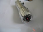
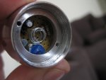
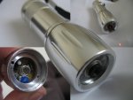
£2 Host from Tesco
16x DVDRW diode from pioneer
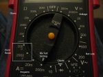
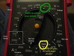
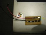
Homebuilt DDL aka LM317 Driver.

Anyway, Having researched continuously for weeks on how to guides, I finally completed my first build.

Heres some pics

I know the lase is very dim thats because I got carried away with my new toy and drained the batts.


Great forum lots of usefull info

Thanks all.

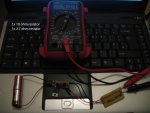
EDIT I have now included an AVI Movie for your veiwing pleasure. The Laser pointer in question has an updated Home Made Driver using an AMS1117 Regulator which can supply upto 1 Amp, The target is a single peice of Black Electrical Insulation Tape

Enjoy

If you like it make a comment
 

Attachments

  • HomeBuild 0.jpg
    HomeBuild 0.jpg
    79.6 KB · Views: 268
  • HomeBuild 1.jpg
    HomeBuild 1.jpg
    138 KB · Views: 353
  • HomeBuild 2.jpg
    HomeBuild 2.jpg
    129.7 KB · Views: 344
  • movie 6.avi
    11.6 MB · Views: 91
Last edited:


Kevlar

0
Joined
Apr 26, 2010
Messages
1,353
Points
48
This is pretty good for your first build!! Very nice. You went about it the right way and did your research first instead of just coming onto the forum asking everyone to TELL you how to do it or having other people do the research for you...

For that you deserve some rep, +1.

I hope other people new into the hobby will see this and learn the right way of doing things. You sir will fit in nicely here.
 
Joined
Sep 29, 2010
Messages
93
Points
0
Kevlar Thank you sir, I wasn't expecting any rep just yet so thanks again I hope to have more builds added in the near future.

My other build is a 1W 445Nm Build a laser kit from *****************.com got the Kit except the 1w diode was missing, hope to be sorted soon. I may have been a little offish with the message I sent in relation to the missing LD. I'm sure they'll sort it pretty quickly.
 

Kevlar

0
Joined
Apr 26, 2010
Messages
1,353
Points
48
I know the guy who owns that store. He is a decent guy, it must have been an oversight, I'm sure he will take care of you.
 
Joined
Sep 29, 2010
Messages
93
Points
0
Yeah, As soon as I messaged him I got a refund on shipping of one of the items pretty much instantly so good on him for that.

A question.

I built a dummy load, when I connect it to a few LM317 drivers I built, the readings are way off, does the readout depend on the battery voltage?

Icluded a Pic
 

Attachments

  • DummyLoad.jpg
    DummyLoad.jpg
    188.3 KB · Views: 244
Last edited:
Joined
Dec 23, 2008
Messages
3,948
Points
63
+1 on your first build very nice

please take a couple pics of your power supply and your driver hooked up to your dummy load. as long as you apply the correct voltage for your driver your dummy load should be fine.

michael.
 
Joined
Sep 29, 2010
Messages
93
Points
0
chipdouglas Thank you

Heres the pic

I know its crude, I apologise for that

Power source is from 2x cr2 batteries producing 5.92v combined.

My calculations get me to 98.42Ma, as you can see the DMM states that the Ma draw is 40.1Ma, Worked out using Ohm's Law:-

LM Ref V Total of resistors
1.25 / 12.7 Ohms * 1000 = 98.425197

Can't think of any other useful info to include.

Oh yes and the pot is a 100ohm, turned up full (No resistance I presume)

Thanks for replies
 

Attachments

  • Dummy Load Setup.jpg
    Dummy Load Setup.jpg
    159.5 KB · Views: 285
Last edited:

Kevlar

0
Joined
Apr 26, 2010
Messages
1,353
Points
48
I can't quite tell from your picture, do you have your DMM set on mA or mV?
 
Joined
Jul 30, 2010
Messages
215
Points
0
Aren't CR2's 3.6V, so 2x should give you 7.2V? You also mentioned in your first thread that the laser is dim because the batteries are drained, so maybe you just need to charge them:)

Also you can try connecting the DMM in series with the test-load and setting it to read mA directly.

Also great 1st build, very cleanly made! +1 rep from me, even tho I only have 1 point to give anyway:)
 

Kevlar

0
Joined
Apr 26, 2010
Messages
1,353
Points
48
as comradmax said, you could connect the DMM in series with the test-load and setting it to read mA directly but if you are measuring across the resistor, you DMM needs to be set to V

EDIT: Hey, I just noticed, a fellow Bostonian!!! :beer: I'm actually in Western Mass but its a small state. I think your the first!! Now I don't feel so lonely. :crackup::crackup:

Never mind, I got them mixed up, I think it depends on the battery. I've seen them in 3.0V and 3.6V.
 
Last edited:
Joined
Jul 30, 2010
Messages
215
Points
0
Carl, I just saw Kevlar's post and looked at your pic again. It looks to me like you do have the DMM set to measure mA, but you need mV. What you have there is measuring current through the DMM:) So you are prolly getting that ~100mA from the driver, it's just now getting split ~60/40 between the test-load and DMM. The 1Ohm resistor on the test-load is just a trick to allow current reading with a voltage meter, because it's easier to connect it parallel to the resistor while the whole thing is running, no need to disconnect and insert the DMM in series.

Kevlar, you're right, I dont know if i've noticed anyone from MA either! Nice collection of lasers you got there... I need to get/make some of my own, maybe then we can have an LPF Mass Meet:)
 
Joined
Sep 29, 2010
Messages
93
Points
0
Hi

Kevlar

Not sure about DMM setting, but have included a pic Decyphering is appreciated Thanks. Primary cells i'm using and they are 3.0v.

Comradmax

The cells have been changed they are not at full charge as they have had limited use. outputting 5.92v out of a possible 6.0v. Thanks for the rep . much appreciated.

also comradmax Please explain the following quote
'Also you can try connecting the DMM in series with the test-load and setting it to read mA directly'

Connect DMM in series?
Which setting would be Ma?

Carl

Catch you all tommorow thanks sleeptime at 1am
 

Attachments

  • DMM Settings.jpg
    DMM Settings.jpg
    179.3 KB · Views: 206

Toke

0
Joined
Jul 25, 2010
Messages
1,099
Points
0
Yes, it looks like mA setting.
Another mistake to look out for with test loads is the lanes vs. islands issue with print boards. :D (It does happen)

ETA: Connecting in series just means that you take one of the wires from the test load and kind of replace it with the whole DMM. Like remove one test load wire from the driver and stick a meter pin in it's place, then hold the other DMM pin and the free end of the wire together.

Your current/pictured setting is 200 mA, it may be too low and you might blow the DMM fuse.
The 10A setting may work or may have too low resolution to give an accurate reading.
Your best choice to set the DMM for mV and measure across the resistor on the test load.
That is a 180 turn to 2000m.
 
Last edited:
Joined
Jul 30, 2010
Messages
215
Points
0
also comradmax Please explain the following quote
'Also you can try connecting the DMM in series with the test-load and setting it to read mA directly'

There are 4 meters in this picture. 3 read the voltage parallel to the "load", which are the resistors; 1 reads current in series, it breaks the circuit and now all of the electricity is going through it.

Like Toke said, just turn your DMM dial exactly 180 deg:)
 

Attachments

  • edits.jpg
    edits.jpg
    82.5 KB · Views: 174
Joined
Dec 23, 2008
Messages
3,948
Points
63
also you need more volts. your dummy load needs 2.8 and your ld needs over 4. so it is always advised to use the same voltage to set your driver via dummy load that is going to run the laser.
@ comrad.... cr's are generally 3v. and rcr are generally 3.6
 
Last edited:

Kevlar

0
Joined
Apr 26, 2010
Messages
1,353
Points
48
maybe then we can have an LPF Mass Meet:)

That would be cool. I keep hearing about laser meets in FL and other places but none around here. Maybe we could start one up!!

also you need more volts. your dummy load needs 2.8 and your ld needs over 4. so it is always advised to use the same voltage to set your driver via dummy load that is going to run the laser.
@ comrad.... cr's are generally 3v. and rcr are generally 3.6

Actually he is using a 16X Diode, I think these are the same "Senkat Reds" which, I thought, only needed 3V. So 3V is needed for the driver and 3V for the diode. I would say 6V minimum. You should always try and get as close to the required voltage as you can. If it was me, I would probably go a smidge over, say 2X3.6V Li Ions because as soon as you hook it up, the battery voltage will start to drop and you won't get that much run time. The extra voltage you feed it will get dissipated as heat from the driver. You could always put a small heatsink on the LM317 chip for that.

And set you DMM according to the pic comradmax posted, then re-test. :D


Top