

Hello I'm sebastien, ham call F4GRX
I'm new here, I want to share my beginner experiments and get advices from you. It seems you have the best laser forum of the intarwebs!
I have to say that lasers are only one of my hobbies, so I play with them from time to time. There are so many things to do! Radio for example! or PIC programs!
First of all I browsed other "hello" threads and unfortunately no, I don't have safety googles yet, but I read the "1000mW blue laser retina damage" story, and I was quite scared, so one on my initial questions is about this. All my experiments so far were with relatively small (but yet dangerous, I know) diodes.
As a beginner in the laser world, I'm quite hesitant to invest $100+ on googles; I would need a pair to protect from blue lasers, and another one for red lasers.
I saw the nice "orange" model on amazon, I'll get it soon to continue my hobby research on blue lasers, but I need advice for "blue" googles to protect my eyes from red lasers. On ebay, I see that "CE" advertised googles are at least $30, but sometimes it just means "china export". Maybe cheaper googles are still ok? Do you have any advice on red-laser googles?
For example what about these? eBay | 638nm 650nm 660nm Red Laser Protection Goggles Safety Glasses Eyewears
Some time ago when I still was a physics student (2004), I got into a laser diode harvesting operation, gathering diodes from discarded laser printers. I learnt it was infrared diodes after a quick google search. I powered one of the mounted IR diodes with a LM317 system, in a shoebox, and monitored the thing with a webcam! I noticed it was not so dangerous if handled properly, so I dropped the shoebox and played a bit with IR lasers. But that was not very interesting, since I needed a webcam to see the spot. But I also got a bunch of very nice laser diode mounts!
In 2010, after a lot of other occupations, I came across the famous SAM's laser FAQ, I knew that DVD used red visible diodes, but I discovered that DVD burners used *powerful* red diodes. This brought me back to the laser hobby and I started gathering "dead" DVD drives from around me (people were really curious about what I could do with them!)
I finally got a decent red laser diode from a dvd burner (some of these are not in a standard package, which is quite disappointing), which I installed in a laser printer diode mount, and this was my first serious homemade laser pointer. It was rather powerful since I could see the beam when pointed outside of my window, thanks to the diffusion on the faint outside air humidity.
Then came the blue laser diode, and by chance I got one from a broken blu-ray drive (not a recorder) in 2012.
Recently, I mounted my blue diode in an old laser printer diode mount, and powered that with an LM317, which resulted in a very nice, but not very powerful, blu-ray pointer. I noticed that the blue pointer activated glow-in-the-dark paint, and other fluorescent product like white paper and clothes. Awesome! Then I discovered that oil was also fluorescing (yellow) and olive oil was producing a red glow!
A few weeks ago, I wanted to create a driver that was more intelligent than a simple LM317. I reviewed schematics from sam's laser faq, and tried to understand photodiode power feedback. But I did not like that because I had diodes with different wirings (dvd diodes are often common-cathode, and no simple driver could work with that) and I could not imagine a simple schematic to use the internal photodiode in all possible situations.
I let that go and focused on constant current drivers.
In another project, I had built a constant current driver for a YIG microwave oscillator, so I reused that. It was based on a bipolar transistor whose base was driven by an op amp comparing the voltage on a shunt resistor and a voltage set by a potentiometer. This driver worked okay with the test LED, but I burnt 4 diodes, including the blue one
Re-reading sam's FAQ, I understood that transient current spikes at driver's startup were the problem, and I noticed a "soft start" circuit could be used.
So here I am, I now have a working driver using a soft-start circuit, a maxim rail to rail "precision" op amp, a n-channel FET instead of a bipolar transistor, and the same potentiometer. I added RC networks in a few places to prevent transients. The current is limited to 80mA because of the 8-Volts regulated supply. The new dvd burner red diode I tested with this driver is still alive
So, I have another question here:
The soft start circuit is strange. Input is 12V, but output is 9V... It worked when I tested with a simple LED, but now the transistor does not seem to saturate when I connect a LD. I think the BD175 transistor does not have enough current gain so the base current is not sufficient to turn the transistor full-on? I used a 33K resistor and a 47uF capacitor to have plenty of startup time. Would a darlington solve the base current problem?
One of the biggest mysteries in front of me right now is: how to know the maximum current I can feed in a diode? I can estimate the threshold current when I see the light output "step", but how to know the maximum current? Sam's FAQ says 10% over the threshold is a maximum, but that does not seem much. Any thoughts about that?
Next question is how to measure the light output. I saw on this forum that the best power detectors use photopiles, but I don't have that. I have some BWP34 photodiodes. Do you know any use of that component to measure laser power? I think a relative measurement is OK for a start, I'll calibrate later
Final question is about diode mounts. I got a nice (and cheap) "C-mount" with a massive aluminium body and a 16-mm lens. I built a small brass thingy to mount a normal 5.6mm diode inside, and tried to focus the beam. I was a bit disappointed, because I could not get a nice spot. I think that this mount is not very efficient because of internal reflections. Do anyone of you have experience with this sort of mount? How are you using them? As of now, the old laser printer thing does a better job! I think this "C-mount" has a lens with a too long focal length, so it does not intercept the full beam.
BTW, I ordered a pair of 12mm Aixiz mounts to check if that's better.
Okay, I wrote a lot, so here are some pictures to let you see what I did!
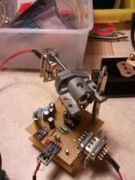
best mount so far, from a laser printer, with a 5mm lens and a red diode.
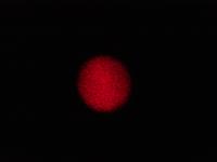
laser spot from this mount, photographed with a sony dsc-f826, 1/2000th of a second, black background, 2 meters distance
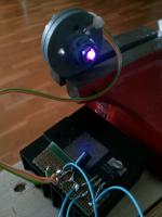
blue diode mount before the diode died (but I found other ones on ebay)
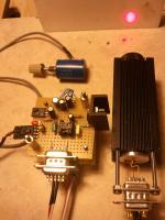
the working driver, and the not-so-nice "C-mount" case
brass mount to fit the 5.6mm diode in the "c-mount" case
http://www.mirari.fr/deCi
another nice mount from a printer, but the lens aperture is very small and it's made for a 9mm diode!
http://www.mirari.fr/iyUC
same one, with a nice brass 9mm to 5.6mm a friend made for me
http://www.mirari.fr/rdeM
nice looking laser diode killer... now dismantled!
http://www.mirari.fr/piru
blu ray beam generating fluorescence in walnut oil!
http://www.mirari.fr/ge4p
fun with a block of glass. the glass is fluorescent on the optical path.
http://www.mirari.fr/muvN
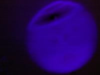
light output from the un-focussed burnt blue ray diode...
light output from the un focussed burnt red diode... the diode has floaters! it's not dust, there is nothing between the bare diode package and the wall!
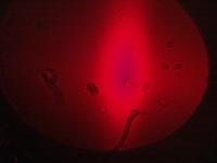
Is that what you call COD?
In the coming weeks I'll try to improve my driver by using a high-side current sensing circuit from TI. This will allow me to ground the FET source and use a smaller value shunt resistor. I'll also have a look at the soft-start problem, and build a photodiode amplifier to test my BWP34, which I just glued on a black heatsink.
best regards!
I'm new here, I want to share my beginner experiments and get advices from you. It seems you have the best laser forum of the intarwebs!
I have to say that lasers are only one of my hobbies, so I play with them from time to time. There are so many things to do! Radio for example! or PIC programs!
First of all I browsed other "hello" threads and unfortunately no, I don't have safety googles yet, but I read the "1000mW blue laser retina damage" story, and I was quite scared, so one on my initial questions is about this. All my experiments so far were with relatively small (but yet dangerous, I know) diodes.
As a beginner in the laser world, I'm quite hesitant to invest $100+ on googles; I would need a pair to protect from blue lasers, and another one for red lasers.
I saw the nice "orange" model on amazon, I'll get it soon to continue my hobby research on blue lasers, but I need advice for "blue" googles to protect my eyes from red lasers. On ebay, I see that "CE" advertised googles are at least $30, but sometimes it just means "china export". Maybe cheaper googles are still ok? Do you have any advice on red-laser googles?
For example what about these? eBay | 638nm 650nm 660nm Red Laser Protection Goggles Safety Glasses Eyewears
Some time ago when I still was a physics student (2004), I got into a laser diode harvesting operation, gathering diodes from discarded laser printers. I learnt it was infrared diodes after a quick google search. I powered one of the mounted IR diodes with a LM317 system, in a shoebox, and monitored the thing with a webcam! I noticed it was not so dangerous if handled properly, so I dropped the shoebox and played a bit with IR lasers. But that was not very interesting, since I needed a webcam to see the spot. But I also got a bunch of very nice laser diode mounts!
In 2010, after a lot of other occupations, I came across the famous SAM's laser FAQ, I knew that DVD used red visible diodes, but I discovered that DVD burners used *powerful* red diodes. This brought me back to the laser hobby and I started gathering "dead" DVD drives from around me (people were really curious about what I could do with them!)
I finally got a decent red laser diode from a dvd burner (some of these are not in a standard package, which is quite disappointing), which I installed in a laser printer diode mount, and this was my first serious homemade laser pointer. It was rather powerful since I could see the beam when pointed outside of my window, thanks to the diffusion on the faint outside air humidity.
Then came the blue laser diode, and by chance I got one from a broken blu-ray drive (not a recorder) in 2012.
Recently, I mounted my blue diode in an old laser printer diode mount, and powered that with an LM317, which resulted in a very nice, but not very powerful, blu-ray pointer. I noticed that the blue pointer activated glow-in-the-dark paint, and other fluorescent product like white paper and clothes. Awesome! Then I discovered that oil was also fluorescing (yellow) and olive oil was producing a red glow!
A few weeks ago, I wanted to create a driver that was more intelligent than a simple LM317. I reviewed schematics from sam's laser faq, and tried to understand photodiode power feedback. But I did not like that because I had diodes with different wirings (dvd diodes are often common-cathode, and no simple driver could work with that) and I could not imagine a simple schematic to use the internal photodiode in all possible situations.
I let that go and focused on constant current drivers.
In another project, I had built a constant current driver for a YIG microwave oscillator, so I reused that. It was based on a bipolar transistor whose base was driven by an op amp comparing the voltage on a shunt resistor and a voltage set by a potentiometer. This driver worked okay with the test LED, but I burnt 4 diodes, including the blue one
Re-reading sam's FAQ, I understood that transient current spikes at driver's startup were the problem, and I noticed a "soft start" circuit could be used.
So here I am, I now have a working driver using a soft-start circuit, a maxim rail to rail "precision" op amp, a n-channel FET instead of a bipolar transistor, and the same potentiometer. I added RC networks in a few places to prevent transients. The current is limited to 80mA because of the 8-Volts regulated supply. The new dvd burner red diode I tested with this driver is still alive
So, I have another question here:
The soft start circuit is strange. Input is 12V, but output is 9V... It worked when I tested with a simple LED, but now the transistor does not seem to saturate when I connect a LD. I think the BD175 transistor does not have enough current gain so the base current is not sufficient to turn the transistor full-on? I used a 33K resistor and a 47uF capacitor to have plenty of startup time. Would a darlington solve the base current problem?
One of the biggest mysteries in front of me right now is: how to know the maximum current I can feed in a diode? I can estimate the threshold current when I see the light output "step", but how to know the maximum current? Sam's FAQ says 10% over the threshold is a maximum, but that does not seem much. Any thoughts about that?
Next question is how to measure the light output. I saw on this forum that the best power detectors use photopiles, but I don't have that. I have some BWP34 photodiodes. Do you know any use of that component to measure laser power? I think a relative measurement is OK for a start, I'll calibrate later
Final question is about diode mounts. I got a nice (and cheap) "C-mount" with a massive aluminium body and a 16-mm lens. I built a small brass thingy to mount a normal 5.6mm diode inside, and tried to focus the beam. I was a bit disappointed, because I could not get a nice spot. I think that this mount is not very efficient because of internal reflections. Do anyone of you have experience with this sort of mount? How are you using them? As of now, the old laser printer thing does a better job! I think this "C-mount" has a lens with a too long focal length, so it does not intercept the full beam.
BTW, I ordered a pair of 12mm Aixiz mounts to check if that's better.
Okay, I wrote a lot, so here are some pictures to let you see what I did!
best mount so far, from a laser printer, with a 5mm lens and a red diode.
laser spot from this mount, photographed with a sony dsc-f826, 1/2000th of a second, black background, 2 meters distance
blue diode mount before the diode died
(but I found other ones on ebay)the working driver, and the not-so-nice "C-mount" case
brass mount to fit the 5.6mm diode in the "c-mount" case
http://www.mirari.fr/deCi
another nice mount from a printer, but the lens aperture is very small and it's made for a 9mm diode!
http://www.mirari.fr/iyUC
same one, with a nice brass 9mm to 5.6mm a friend made for me
http://www.mirari.fr/rdeM
nice looking laser diode killer... now dismantled!
http://www.mirari.fr/piru
blu ray beam generating fluorescence in walnut oil!
http://www.mirari.fr/ge4p
fun with a block of glass. the glass is fluorescent on the optical path.
http://www.mirari.fr/muvN
light output from the un-focussed burnt blue ray diode...
light output from the un focussed burnt red diode... the diode has floaters! it's not dust, there is nothing between the bare diode package and the wall!
Is that what you call COD?
In the coming weeks I'll try to improve my driver by using a high-side current sensing circuit from TI. This will allow me to ground the FET source and use a smaller value shunt resistor. I'll also have a look at the soft-start problem, and build a photodiode amplifier to test my BWP34, which I just glued on a black heatsink.
best regards!
Last edited:


