Welcome to Laser Pointer Forums - discuss green laser pointers, blue laser pointers, and all types of lasers

LPF Donation via Stripe | LPF Donation - Other Methods

Links below open in new window

ArcticMyst Security by Avery

New (lower priced) source for 473nm modules?

Sowee7

Active member
Joined
Feb 1, 2021
Messages
439
Points
43
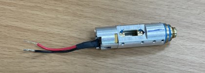
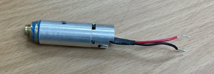
it seems like I have found a new source to get 473nm modules for a good price, they are inside DPBL-9010F lab laser. The modules have a diameter of 17mm and they are 60mm in length. They are inside a metal housing that has a photodiode feedback sensor, thermistor and a collimating/expanding lens set. They produce 10+ mw of 473nm light, i managed to get one for $120 but there are a few up for sale for $249, still way cheaper than how cni sells them now ($700),
here are some links:
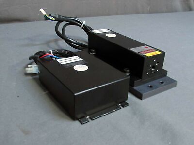


kecked

0
Joined
Jun 18, 2012
Messages
952
Points
63
How is the beam? I bought those bw spectrometers for the 473 and the beam is horrible. Such a pretty color. Really nice in lumia
 

Sowee7

Active member
Joined
Feb 1, 2021
Messages
439
Points
43
Here is some pictures of the module, i zoomed into it a bit
 

Attachments

  • A9C10B71-43C8-4D25-9B1C-2C003B365C1C.jpeg
    A9C10B71-43C8-4D25-9B1C-2C003B365C1C.jpeg
    790.3 KB · Views: 19
  • 31075B49-866B-4AA4-AAF3-4D18CE96189A.jpeg
    31075B49-866B-4AA4-AAF3-4D18CE96189A.jpeg
    772 KB · Views: 19

Sowee7

Active member
Joined
Feb 1, 2021
Messages
439
Points
43
How is the beam? I bought those bw spectrometers for the 473 and the beam is horrible. Such a pretty color. Really nice in lumia
The beam is quite good actually, it’s in TEM00 and has a nice thin beam
 

Lumenati

New member
Joined
Feb 26, 2020
Messages
8
Points
3
Just the post I was hoping to see, though I'm a bit late. I had a quick question if you don't mind, do you know the pinout for the input on the driver? I have tried 12V DC 2A on the "+12V" and "-12V" on the board (red and blue wires), as well as 12V DC 2A on the red and black wires. The light on the driver lights up in both cases, but no laser (and 0V on the LD pins). I know the 2 center pins are bridged, and I know they are ground. I'm assuming the blue pin is an "enable" pin of sorts, but I don't want to guess by just bridging the blue and black wires, with my luck ill fry something. The 2 center pins are labeled "0V" on the board. Any help would be really appreciated, I want to test this thing ASAP and there's zero information online
 

Attachments

  • 20230630_134210.jpeg
    20230630_134210.jpeg
    192.7 KB · Views: 4
Last edited:

farbe2

Well-known member
Joined
Oct 3, 2018
Messages
303
Points
63
You need - and + 12V so essentially 24V center tapped.

Or two 12V supplies with one connected between +12V and GND and one between GND and -12V.
The lower supply needs to be floating in that case.
 

Lumenati

New member
Joined
Feb 26, 2020
Messages
8
Points
3
You need - and + 12V so essentially 24V center tapped.

Or two 12V supplies with one connected between +12V and GND and one between GND and -12V.
The lower supply needs to be floating in that case.
Thanks for the response, so if I were operating with 24V DC, the connections would be positive/positive, and negative/ground bridged to -12v? I'm not experienced with these types of circuits, feeling kinda dumb right now
 

Lumenati

New member
Joined
Feb 26, 2020
Messages
8
Points
3
Or two 12V supplies with one connected between +12V and GND and one between GND and -12V.

I'm well aware of positive and negative, but that's why I'm confused. How can there be a standalone 12V power supply over 2 negatives; if I were using 2 12v power supplies like you said? And how is it a center tapped circuit if the 3 wires on the right would share the same ground? Maybe im just overthinking it. I came here because he actually has the unit and might point me in the right direction, I did do research first. I know this is a basic problem, but this was an expensive laser and I don't want to ruin it, the reason I did research first was so nobody here would give me a hard time over it. I've built many lasers with various driver types, I've repaired logic boards on computers for years, and I have a good understanding of driver circuits and how they work. This is my first lab laser, I'm just trying to play it safe, because this model has no publicly available information. It's a Suwtech Inc. LDC-1540XP Direct Current (DC) Driver, which calls for 12V (so I was told) not 24V. Not sure why you'd rather try to make me feel stupid, I already do
 
Last edited:
Joined
Sep 20, 2013
Messages
17,462
Points
113
I have yet to see any drivers for DPSS lasers that need a positive and equally negative power source. I suppose it could be possible, but can't think of a good reason for one.
 

farbe2

Well-known member
Joined
Oct 3, 2018
Messages
303
Points
63
I've repaired logic boards on computers for years, and I have a good understanding of driver circuits and how they work
Then you must know that PCs also use -12V, +12V, ground, old ones even use -5V. (RS232-serial / PCI)

connector_atx_pinout.GIF

Please do yourself the favor and google negativ/positive power supply.
It's not ground. There are actually 3 wires. Research center tap.
You dont need to connect "both" -12V and gnd, they are not the same.


I have yet to see .... lasers that need a positive and equally negative power source ........ can't think of a good reason for one.
It's often the TECs. A designer can use a full bridge to switch the tec from cooling to heating an vice versa.
However sometimes a fullbrigde is omitted for cost/space constrains and/or if the system has +-supplys available.
A differential modulation input might also need a +-supply.
 

Lumenati

New member
Joined
Feb 26, 2020
Messages
8
Points
3
Ok. I made a little diagram based on what I think it might be, drew it a couple different ways. I'm using 12v batteries as a reference, but if someone can just give confirmation that'd be awesome. The lines represent connections, and the pins represent the pins, based on their layout in the first photo. Does it look right? Or am I actually dumb20230703_011130.jpg
 

Lumenati

New member
Joined
Feb 26, 2020
Messages
8
Points
3
Then you must know that PCs also use -12V, +12V, ground, old ones even use -5V. (RS232-serial / PCI)

It really doesn't take a genius to read a schematic, check values, diagnose and replace the necessary components when you're only testing 1 rail, against ground. Its not rocket science, I know of positive and negative voltage, but I don't know if it's earth or case-ground, or ground for the circuit. If its earth ground, who cares? But if its ground for the circuit, negative from the battery and positive 12v (on a black wire) would be fed into it. That's why I was confused.
 

kecked

0
Joined
Jun 18, 2012
Messages
952
Points
63
Paul there likely are opamp circuits in the circuit for who knows what. Many need a bipolar supply. If the tec for example has a comparator made of opamps it might need it. Same with current control. Most times you just add a chip to flip the script for you and generate the negtive voltage when you need it cuz you generally only need a 100ma tops. That’s a guess of course for why.

like you said equally negative voltage yes. Current unlikely.

I know it says 12v but just as a test take 2 9v batteries and try it.
 
Joined
Sep 20, 2013
Messages
17,462
Points
113
Paul there likely are opamp circuits in the circuit for who knows what. Many need a bipolar supply. If the tec for example has a comparator made of opamps it might need it. Same with current control. Most times you just add a chip to flip the script for you and generate the negtive voltage when you need it cuz you generally only need a 100ma tops. That’s a guess of course for why.

like you said equally negative voltage yes. Current unlikely.

I know it says 12v but just as a test take 2 9v batteries and try it.

I've been working with op amps since the early 1970s. You don't need a negative supply to make them work. Just less positive than the supply voltage or the + input. And, of course, these use very little current. That's not the point. My point was that I haven't seen drivers that need a negative supply included with an equally positive supply.


Top