I'm new to lasers, only have a few thus far, but i'm trying to figure out the best way to determine the beam profile, or really just the primary diameter. Power isn't my primary concern, but of course using my techniques changing the power appears to change the size, although i'm not sure how much is just diffusement into the surface or what not.
Let me show you what i've done, and show you some pictures to illustrate, hopefully I can attach pictures here. All beams are 10 inches away, focused by hand, the usb microscope is pointing straight down and the laser is coming in at about 30 degree angle. Using a Mastech digital desktop power supply in constant amp mode, just modifying the amps. The laser I have is from DTR: "12X S06J Bluray Diode In Copper Module W/Microboost & 405-G-2 Glass Lens" So 405nm
I'll describe the pictures under the picture.

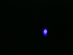
This is the first beam, 100mah, 2.1volts. I'm not sure how to upload will scale, but 37 pixels is 1mm, and on this picture, the beam was basically about 1mm, maybe a little less, like 0.85mm. That was all the focused I could get it.

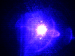
Same exact beam and settings and I just moved the welders mask away. Oh yea, I was holding the welders mask close to the laser, that part of the beam is much larger as it's converging down before the focus point. It's about 2.5mm in the pic, but this is what confused me, it was the same focus, same distance, just the welding filter removed, so are we seeing lots of laser diffuse at the impact point (i don't know what terms to use haha) or is it really that size? I have no idea.

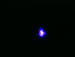
This is at 0.25amp, volts still read 2.1v, this is through the welders filter, and the beam appears to be 1.4mm

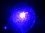
This is 0.25amp, with no welding filter, it seems like it's about 2.3mm, which is less then the other lower power one, but I'm sure I moved and re-focused a bit, so this is all just an estimation.
The only thing I can tell you that seems much smaller is the burn marks in the paper, some of the burn points and burn lines are 0.1mm, but that doesn't mean the beam only touched that spot
I looked into beam profilers, they all seem to be extremly expensive, like $2500 or more. edmunds optics has one for $2500, but that seems a bit much, was hoping there was some more reasonable solutions. I might consider one at $1000, but I dunno, perhaps i'm putting to much into the focusing of the beam. I also read about a technique using Logitech webcams in some special bayer mode, which might be kind of how the professional tools do it, but I couldn't find anybody who's actually done it, only info on potentially how to do it.
I'm working on a 3d printer using SLA, stereolithography with the laser and a galvo scanner, or some control technique similar to a galvo scanner. The focal distance will be about 10 inches away, and vary about half an inch, so like 10 to 10.5 inch, in that span, I want to have a small laser beam of course. Actually 1mm might not be to bad, and it might actually be what I want, but the point is I don't know if that's the case or not with my techniques. 1mm laser beam into UV curable resin is kinda like having a CNC machine with a 1mm end mill, which of course gives outstandingly accurate results. I've tested the beam in to the UV resin and it seems to work quite nicely, even at lower settings, but doing it by hand it hard to determine
One technique I juse thought of, I should focus the beam at the 10 inch point to the best I can by hand. Then shoot the beam 10 feet and measure the diamter, and then 15 feet and measure it, I can determine the diverging angle, and trace back to where the focus point should be... well actually that doesn't neccisarily tell me the size at the focus point, since the laser and optics aren't perfect, so it won't be perfect at the focus point, but it might tell me that I do have it focused at the right point... dunno.
So, basically, how do you guys measure beam size/profile? Just looking for some help. And if my technique is totally, wrong please tell me.
Thanks,
Ross
Let me show you what i've done, and show you some pictures to illustrate, hopefully I can attach pictures here. All beams are 10 inches away, focused by hand, the usb microscope is pointing straight down and the laser is coming in at about 30 degree angle. Using a Mastech digital desktop power supply in constant amp mode, just modifying the amps. The laser I have is from DTR: "12X S06J Bluray Diode In Copper Module W/Microboost & 405-G-2 Glass Lens" So 405nm
I'll describe the pictures under the picture.

This is the first beam, 100mah, 2.1volts. I'm not sure how to upload will scale, but 37 pixels is 1mm, and on this picture, the beam was basically about 1mm, maybe a little less, like 0.85mm. That was all the focused I could get it.

Same exact beam and settings and I just moved the welders mask away. Oh yea, I was holding the welders mask close to the laser, that part of the beam is much larger as it's converging down before the focus point. It's about 2.5mm in the pic, but this is what confused me, it was the same focus, same distance, just the welding filter removed, so are we seeing lots of laser diffuse at the impact point (i don't know what terms to use haha) or is it really that size? I have no idea.

This is at 0.25amp, volts still read 2.1v, this is through the welders filter, and the beam appears to be 1.4mm

This is 0.25amp, with no welding filter, it seems like it's about 2.3mm, which is less then the other lower power one, but I'm sure I moved and re-focused a bit, so this is all just an estimation.
The only thing I can tell you that seems much smaller is the burn marks in the paper, some of the burn points and burn lines are 0.1mm, but that doesn't mean the beam only touched that spot
I looked into beam profilers, they all seem to be extremly expensive, like $2500 or more. edmunds optics has one for $2500, but that seems a bit much, was hoping there was some more reasonable solutions. I might consider one at $1000, but I dunno, perhaps i'm putting to much into the focusing of the beam. I also read about a technique using Logitech webcams in some special bayer mode, which might be kind of how the professional tools do it, but I couldn't find anybody who's actually done it, only info on potentially how to do it.
I'm working on a 3d printer using SLA, stereolithography with the laser and a galvo scanner, or some control technique similar to a galvo scanner. The focal distance will be about 10 inches away, and vary about half an inch, so like 10 to 10.5 inch, in that span, I want to have a small laser beam of course. Actually 1mm might not be to bad, and it might actually be what I want, but the point is I don't know if that's the case or not with my techniques. 1mm laser beam into UV curable resin is kinda like having a CNC machine with a 1mm end mill, which of course gives outstandingly accurate results. I've tested the beam in to the UV resin and it seems to work quite nicely, even at lower settings, but doing it by hand it hard to determine
One technique I juse thought of, I should focus the beam at the 10 inch point to the best I can by hand. Then shoot the beam 10 feet and measure the diamter, and then 15 feet and measure it, I can determine the diverging angle, and trace back to where the focus point should be... well actually that doesn't neccisarily tell me the size at the focus point, since the laser and optics aren't perfect, so it won't be perfect at the focus point, but it might tell me that I do have it focused at the right point... dunno.
So, basically, how do you guys measure beam size/profile? Just looking for some help. And if my technique is totally, wrong please tell me.
Thanks,
Ross


