Welcome to Laser Pointer Forums - discuss green laser pointers, blue laser pointers, and all types of lasers

LPF Donation via Stripe | LPF Donation - Other Methods

Links below open in new window

ArcticMyst Security by Avery

why no 2.2A 16.8mm round driver

Garoq

0
Joined
Aug 27, 2010
Messages
1,525
Points
83
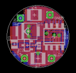
That's a good question. Maybe not enough people have voiced a demand for them. SL has some but they aren't selling them separately, only in a driver and pill assembly for an expensive $44.99. DIY 2.2A Driver & Pill Module
Someone needs to have a large number of these made and sell them at a reasonable price.

The drivers are expensive because I only had a very small number produced so far. I plan to have a larger quantity of these made and available at a reasonable price ASAP.

9263246751_86dc476a0c_z.jpg


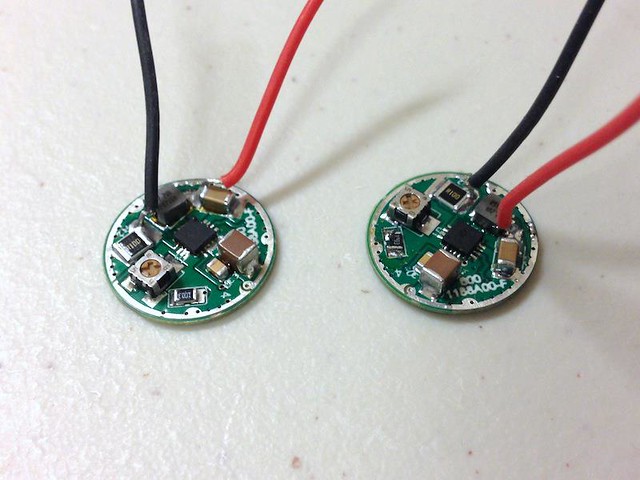
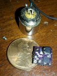
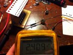
BTW these drivers are currently adjustable in the range of about 1.6 to 2.3A. They are in fact 16.8mm in diameter and fit a C6-style brass ring. If there is interest I will make them available in two or more ranges that will cover a wider spectrum of mA capability.
 
Last edited:


benmwv

0
Joined
Sep 10, 2010
Messages
1,380
Points
48
Heres a new version based on the tps54332 buck regulator! This one is much better:
-main IC avaliable on digikey
-powerpad on bottom of IC for heat dissipation
-continuous ground
-pot adjustable output

Unfortunately I had to pack pretty tight and use some (well 6) 0402 sized components to fit this more complex circuit on to a 16.75mm board. Don't worry guys they really aren't that bad. I have soldered 0201 by hand with a huge tip radioshack iron before, reflowing 0402 is cake compared to that!

I even had to route one trace all the way across the board along the bottom between the battery contacts haha.

attachment.php


attachment.php


Once I do a few finishing touches and get the silkscreen/part names sorted out I'll post up the files. I just couldn't wait to show you guys haha!

Sam it would be great to have your input on this project. You have a lot of experience here! Totally understand if you would rather stick to your own blitzbuck though.

Garoq those look like nice drivers but one thing scares me. I see a pot but no amplifiers. I hope the main current isn't running through the pot! My guess is that the pot is a voltage divider across the sense resistor. If this is the case, I would warn you never to adjust the pot with a diode connected. If the wiper jumped up for only a split second during adjustment the chip would see 0v on the fb pin and ramp the output to full. This would most likely kill the diode.

I'm not trying to dis the driver or anything, I hope it doesn't come off that way. Just a friendly warning. Got some more details on it? input/output voltages?
 

Attachments

  • benbuck2.PNG
    benbuck2.PNG
    35.9 KB · Views: 781
  • benbuck sch2.PNG
    benbuck sch2.PNG
    12.1 KB · Views: 935
Joined
Jan 14, 2011
Messages
3,816
Points
63
Ben, that looks like a great design. Things are packed pretty tightly on there. Also, I'm never a huge fan of ICs that require external compensation.

I have noted that it's not always a great idea to use the ZXCT1009 in these cases. I don't know how that IC would handle it, but there can always be some pretty nasty spikes on the output unless you really work hard to tame it. On a previous version of the BlitzBuck that caused some diode deaths on my end (several, actually).

Finally, I would be REALLY careful with running that trace around the board in on the bottom. If my gut serves me right, that'll introduce some HUGE noise in the trace because of the switching elements it passes near.

I don't plan on making the BlitzBuck open source because I need a source of income for school, but this is a good development. People don't need to buy a driver if they want to make it themselves!

EDIT: Also, I've been having second thoughts about continuous ground lately. While yes, it makes it useful for a select few diodes, it actually removes the possibility of using a driver for some other diodes. The diodes that it removes the ability to use are often high current IR diodes while the diodes that you can't use are often low-current blu-ray or reds... so I figure that those are better suited for a linear driver anyway. That's why the BlitzBuck V4 will not be continuous ground.
 
Last edited:
Joined
Jun 21, 2012
Messages
2,019
Points
48
wow this tread has come a lot further that I thought it would in just a couple of days!! i'm liking this open source driver, and cant wait to see the fully tested and tuned version! and by adding a pot that just makes it that much better!

+1 to you benmwv
 
Last edited:

benmwv

0
Joined
Sep 10, 2010
Messages
1,380
Points
48
Thanks awillis!

Ben, that looks like a great design. Things are packed pretty tightly on there. Also, I'm never a huge fan of ICs that require external compensation.

I have noted that it's not always a great idea to use the ZXCT1009 in these cases. I don't know how that IC would handle it, but there can always be some pretty nasty spikes on the output unless you really work hard to tame it. On a previous version of the BlitzBuck that caused some diode deaths on my end (several, actually).

Finally, I would be REALLY careful with running that trace around the board in on the bottom. If my gut serves me right, that'll introduce some HUGE noise in the trace because of the switching elements it passes near.

I don't plan on making the BlitzBuck open source because I need a source of income for school, but this is a good development. People don't need to buy a driver if they want to make it themselves!

EDIT: Also, I've been having second thoughts about continuous ground lately. While yes, it makes it useful for a select few diodes, it actually removes the possibility of using a driver for some other diodes. The diodes that it removes the ability to use are often high current IR diodes while the diodes that you can't use are often low-current blu-ray or reds... so I figure that those are better suited for a linear driver anyway. That's why the BlitzBuck V4 will not be continuous ground.

I had second thoughts about that trace too. That was just the only way I could do it. I thought that maybe it would be OK since it is directly beneath ground the whole way, and never actually goes under the switching area. Only testing will tell.

I agree about external compensated chips. They suck. Its hard to find a good high current IC that isn't externally compensated though. Hopefully I dont have those problems with the zxct1009. Going for a straight resistor with this chip would kill efficiency. The sense voltage is 0.8v.

This driver is mainly aimed for 9mm 445nm diodes so the continuous ground is helpful.

OK guys here are the files. I added all the part values and fixed the silkscreen. Also some minor board tweaks.

Forgot to mention before this board has soft start! A with the pot the current range is about 1A-2.8A. Of course this can be easily changed. If you need a specific range you can use this file I made to calculate the fixed resistor and the pot. WAY easier than digging through the zxct1009 datasheet every time. I am using 0.05 ohms for RSENSE (R1 in the diagram). The feedback voltage is 0.8v.

attachment.php
 

Attachments

  • benbuckv2.zip
    41.2 KB · Views: 47
  • zxct1009.PNG
    zxct1009.PNG
    15.8 KB · Views: 1,608
Joined
Jan 14, 2011
Messages
3,816
Points
63
Yeah, if you've noticed from the BlitzBuck, they're always internally compensated AND synchronized rectification. I hate external schottkeys too. AND boost capacitors! Minimizing part count is how I managed to make it so small and allow the resistors/capacitors to be fairly large. Hopefully you don't have those problems either. I think that if you used a big enough SS capacitor, then you might be good.
 

benmwv

0
Joined
Sep 10, 2010
Messages
1,380
Points
48
Yep. I need to go chip hunting and find something with more internal components. But I do like the features this chip has. And its typical switch current limit is 6.5A!

Im on the fence about internal schottkys. Thats a decent amount more heat in the IC itself. I guess it depends whether you have a powerpad.

Have you ever worked with external switch controllers? you can get some serious output from them! Heres a sneek peak at something I will be open sourcing soon:

attachment.php


14mm round (goes inside pill) with external switch. Boost. Powerful. Thats all the info I'm giving for now! haha :eg:
 

Attachments

  • bigboost.PNG
    bigboost.PNG
    8.6 KB · Views: 703
Joined
Jan 14, 2011
Messages
3,816
Points
63
Eh. I've always found that internal schottkys drop a lot less voltage than external ones, so the overall net heat generated by the board will be less. Most internals I work with drop <300mV. But you are right - that is a good amount of heat in the IC package itself... never thought about it that way!

I have attempted to work with an external switch controller before. It was back when I was trying to develop a catch-all BlitzBuckBoost. It didn't work out so well. Apparently, it makes them rather finicky. I have still been looking for ICs that'll do boost internally, but I can never find them. Maybe I'll have to go external for my BlitzBoost =p
 

benmwv

0
Joined
Sep 10, 2010
Messages
1,380
Points
48
The problem with controllers is that they have a lot more external parts which drives up cost and board size.

When you have a lot of internal parts you can make some SMALL drivers. I have a 9x9mm boost/linear that will put out about 1A and can even run from a single 1.5v alkaline battery (low current though). It sits flat behind an aixis module. I use it in my tiniest of tiny builds! It has literally just IC, two caps, inductor, resistor, pot.
 
Joined
Jan 14, 2011
Messages
3,816
Points
63
Yeah, my standard driver is 9x10-12mm or so. Never tried 9x9 before though! Probably could.
 

benmwv

0
Joined
Sep 10, 2010
Messages
1,380
Points
48
Heres a quick picture of my 9x9. This is an dead one a few revs old. With a penny and dusty aixis for scale.

attachment.php


And heres is a pic of that external switch driver. Driving 2.4A into an 8v load with 4.1v input. NO heatsink. Thats about 20W ouput power... It died after about 45 seconds of this torture test.

attachment.php
 

Attachments

  • 9x9old.jpg
    9x9old.jpg
    147.4 KB · Views: 562
  • 14mmround.jpg
    14mmround.jpg
    115.3 KB · Views: 516

IsaacT

0
Joined
Aug 25, 2010
Messages
5,947
Points
83
Hey benmwv, where did you begin learning all of this? And how old are you? Some of the concepts that you seem to have down to second nature are just bonkers.
 

benmwv

0
Joined
Sep 10, 2010
Messages
1,380
Points
48
Back when I was a laser noob i decided I was too cheap to buy flexdrive and Id just make my own boost driver. And thus the benboost was born. I had absolutely no idea how difficult, long, expensive a process it would be though. I learned everything I know about eagle and laser drivers on the fly while me and rhd (also a noob at the time!) were making it. I seriously have over 40 seperate board files for that thing because at the beginning we just didn't know what we were doing.

I am 18. I think i was 15 when I started it.
 
Last edited:

IsaacT

0
Joined
Aug 25, 2010
Messages
5,947
Points
83
That is an impressive accomplishment! Did yall just google everything or take electronics class in high school?
 

benmwv

0
Joined
Sep 10, 2010
Messages
1,380
Points
48
Just googled pretty much. IDK about him but my highschool didnt have any electronics class :( Rhd i think is at least 5 years older than me though.
 

Garoq

0
Joined
Aug 27, 2010
Messages
1,525
Points
83
Garoq those look like nice drivers but one thing scares me. I see a pot but no amplifiers. I hope the main current isn't running through the pot! My guess is that the pot is a voltage divider across the sense resistor. If this is the case, I would warn you never to adjust the pot with a diode connected. If the wiper jumped up for only a split second during adjustment the chip would see 0v on the fb pin and ramp the output to full. This would most likely kill the diode.

I'm not trying to dis the driver or anything, I hope it doesn't come off that way. Just a friendly warning. Got some more details on it? input/output voltages?

The high current on this driver does not go thru the pot.

A pot is considered to have a lower reliability rate than fixed resistors and pots do fail. However, pots are used all over the world in electronics. The probability of something happening like what you describe is extremely remote.

Regardless, I would never recommend that a customer adjust the pot with a diode attached. The proper way to set the current is with a dummy load. Also, it would be fairly awkward to adjust the current while connected to a laser diode, given the relative orientations of the driver pill and the diode which is presumed to be mounted in a heat sink, while keeping the business end of the laser pointed in a safe direction and monitoring the current. ;)

FYI the driver was designed by a military power circuit contractor who has decades of experience. It has an adjustable voltage output of up to 6V with an input of up to 17V, a maximum current output of 3A and was designed primarily for the higher currents required by the M140 and 9mm 445nm diodes.
 
Last edited:


Top