- Joined
- Nov 18, 2009
- Messages
- 269
- Points
- 0
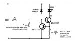
Hey! Check picture of circuit next post
Im thinking in doing a RGB projector, while first im going to get all the diodes working, but as I am thinking in enabling TTL modulation for at least the red and blue lasers (the green would be tricky, due to the fancy optics).
Ive been thinking if anyone (although i searched for it, and came with nothing) tried to do a "dual ddl" driver, just so he/she could get more juice into one of those 445 diodes. I've seen dual flexes, but iirc, no double ddl's.
Why am i asking this?? There is a really simple way of getting the TTL 5V voltage higher (to ur battery/PSU voltage) using a darlington array (we used them in a microcontrollers lab with that exact purpose: 5V in and at out=PSU, 0V in @out=0V) and the datasheet of those ULN2804 can be found here.
At least thats what i think they were doing...i dont know much about electronics...im a big n00b in that field, but i was thinking in having a DDL circuit feeding the bias (threshold) current, and then another DDL circuit delivering the rest of current when turned on/off.
Those ULN2804 are "much cheaper" than a LM317 and it has 8 ins/outs, and if u need more current, u can split ur signal into 2 and use 2outs in series to have 2x load current maximum.
Before even knowing if this is possible my first problem would be "isolating" both DDL circuits from each other, if needed. So that current would only be going to the diode, and not to the other DDL circuit.
I will even take this boat and ask about using a LPC-815 with a DDL driver, as well as a 445 LD (separate driver), and as i would be using a wall-plug AC/DC converter, they would have same '-' (gnd). I read something about problems with different voltage casings, but in this case i dunno if the 445 case has any influence or if not, or the case of them having different cases, which would cause a problem using same ground for the DDL circuits (thats what it seemed from what i read...there would be a problem). And how does the white fusion kit works, if the whole thing is made of Aluminium, the greens module casing is case positive and the reddies is case negative...or are they insulated in any way??
And last question, as more of a safe side then question. Im still thinking if i would lase my reddies both with same current (so series) or if in separate (im doing a dual PBS combined LPC-815). To use a DDL and both LD's connected in series to the DDL i would just need to feed the LM317 with at least ~2x3v(each LPC voltage drop)+1.25V+3V(from LM117)=~10.25V, if iirc everything from that circuit.
Oh! Just last thing, as to the capacitor value (throughout the designs in the internet, that capacitor is in the 10 milifarad range) would start cutting frequencies around the kHz, am i wrong? for TTL modulation, at around 10kHz that would be a problem...and it would have to be pushed to the uF region or even lower, no? Do you reckon voltage spikes to be of higher frequencies than just a few us??, cuz thats in the MHz range and we could keep it off with lets say 10uF...anyone please corect me if im completely wrong...
thanks for reading, and hope i was clear enough.
EDIT
Edited a few errors i had
Last edited: