kiyoukan
0
- Joined
- Oct 24, 2009
- Messages
- 2,555
- Points
- 48
got a spec sheet?
maybe i can get some.
maybe i can get some.


got a spec sheet?
maybe i can get some.
why are they so hard to get or is it price?
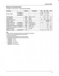
ps that chip has a vdrop of 1V
Output Drop-out Voltage VDP IOUT=1A, VCS-VOUT 1 1.31 V
So thats not lower than the stcs2a
That's great Kiyoukan, but not everyone has access to SMT soldering equipment.
")
That said, you guys really should consider my earlier comment about dropout.
This setup is not going to be 0.5V dropout, it will be 1.75V. It has to be - it relies on that extra 1.25 drop across the resistor for it's essential function.
So, better than an LM317? Yes.
Better than a 1085? Eeeek, maybe by a very tiny bit. 1.75V vs 2V. Unless this is on par cost wise (1085s are under a buck each), then I wouldn't see much benefit to this IC.
But, here's an example:
http://www.addmtek.com/products/pdf/DD077-A705_D.pdf
Dropout voltage of 120mV.
They are awesome ICs.
The quoted Drop Out Voltage for the 8085 is 1.5Volts. Then if you
add the 1.25V drop across the current sense sense resistor you
have a total Voltage Drop of 2.75 Volts for the 8085...
The quoted Drop Out Voltage for the OP's 4 pin regulator is 0.5V
plus the 1.25V drop across the current sense sense resistor gives
you 1.75V... That's a difference of 1 Volt....
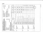
Looking at the specs that Regulator series can only supply a Max
output of 360mA...
The others mentioned here can handle 2-3 Amps... Oranges/Apples
if you will....:beer:
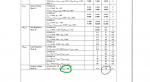
In designing a circuit we use the actual Electrical Characteristics
of a part. Those numbers are normally written in Min Typ Max
format with actual numbers (values).
If for instance we want to know the MAX Violtage that could be
applied to a part in a worst case scenario we will look in the MAX
column.