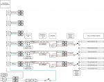
When I recently built a custom HTPC in an old tape deck it made me realize that testing LED's really requires a solid and stable power supply. I am designing and building one now (yes I am a total novice) and would like a sanity check on a few things. Attached is the diagram and the application will be for testing LED's, LCD's, and eventually setting up a laser projector of some type for my stereo system (I think I will use two to three 5 - 8mw lasers at this point so that is what I am trying to design for).
Biggest question is on the smoothing capacitors. It looks to me like, here in the US, if I want to keep the voltage drop under 10% for .5A then I will need 42000uf of capacitance. That seems pretty high considering the power supply I found in a not so old stereo receiver only had two 6800uf capacitors. There is a lot of information on this on the internet but it seems to be more about theory than practice. Any Advice?
Second question, my plan is to do basic AC-DC conversion, smoothing, and regulation in the first half of the PS for outputs that are stable. Then those outputs will feed to manual switches. The switches will alow me to plug into modules that will further refine and smooth the DC power down to the precise power outputs I want. I want to protect the power supply, the modules, and the devices I plug into the final outputs. Should I build the protection in at the output modules since they will provide the final power outputs or in the first half before the power is switched. My thought was the power modules. Also I have assumed that this is overload protection, or is there other terms I should be researching?
If the diagram is too small to read let me know please.