Welcome to Laser Pointer Forums - discuss green laser pointers, blue laser pointers, and all types of lasers

LPF Donation via Stripe | LPF Donation - Other Methods

Links below open in new window

ArcticMyst Security by Avery

Single Pulse Driver Circuit

Fiddy

0
Joined
May 22, 2011
Messages
2,726
Points
63
Good Hello,

I recently acquired some 1:1 replica assualt rifle guns that are plastic and have switches and lights and what not.

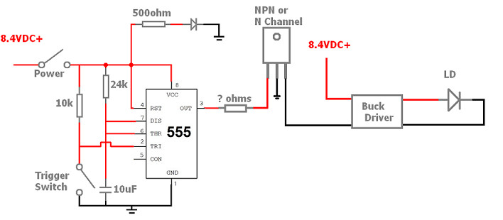
I plan to fit a high power blue laser in the barrel and when i press the trigger it gives a short pulse to a buck driver then turns off.

I was thinking i could do this with a 555 timer in monostable mode?

Attached is my diagram, if anyone is familiar in driving mosfets/transistors from a 555 time and could lend a hand it would be great!

Fiddy.
 

Attachments

  • monstable trigger 5552.PNG
    monstable trigger 5552.PNG
    34.6 KB · Views: 3,774


Fiddy

0
Joined
May 22, 2011
Messages
2,726
Points
63
sweet, i wouldnt know how to match the gate curent to a transistor i pick lol
 
Joined
Dec 11, 2011
Messages
4,364
Points
83
Since it's a DC pulse Rgate can be relatively high, you just don't want to excessively load the 555. R= V/I 50mA is a good ballpark figure. 8.4/0.05 = 168 ohms.

Btw that MOSFET is wired wrong; standard Pinout is GDS, so reverse the center pin and the pin to buck negative. Also don't use a BJT for this as a fet is better for power switching a high current load like a LD driver.

I didn't check your 555 schematic since I don't have monostable retriggerable memorized anymore.


Sent from my iPhone using Tapatalk
 

Fiddy

0
Joined
May 22, 2011
Messages
2,726
Points
63
i plan on using a IRF1405 MOSFET, so the gate resistor would be to limit current from the 555 timer?
also i think the 555 timer is rated for 200mA output
 
Last edited:

djQUAN

0
Joined
May 27, 2013
Messages
1,154
Points
63
In case you didn't know, that circuit will keep the LD on for as long as the trigger is held closed. if the trigger closes for a very short time, only then will it stay on depending on the set time using the R and C value.
 

Fiddy

0
Joined
May 22, 2011
Messages
2,726
Points
63
yeah, but even if the trigger is pressed multiple times during the first pulse it has no effect. im trying to replicate single shot fire from a gun
 
Last edited:
Joined
Dec 11, 2011
Messages
4,364
Points
83
Yep gate resistors in DC pulse systems are to limit dI/dT and dV/dT on the gate to control EMI generation, ringing, and transients, but in this application you want to limit loading of the signal source. It will slow down the discharge of the gate (not super important since the 555 pulls output to ground on off periods) but you can put a reverse biased diode in parallel with Rgate to quickly discharge the gate for applications where the signal source can't sink current as well. If the signal source can't sink current at all then you need a resistor in parallel with the GS junction to discharge it, but mind then that Rgate forms a voltage divider with Rgs so the values used will be critical to ensure sufficient gate drive and keep the 5RC time constant low enough to ensure quick discharge.


Sent from my iPhone using Tapatalk
 
Joined
Dec 17, 2012
Messages
2,081
Points
63
Sig drops the Internet on every post and it's written at a physicist's vocabulary. Lol. I have read some of his things to my wife and she just gives me that "your a nerd look Ido learn a lot from them tthough.
 

djQUAN

0
Joined
May 27, 2013
Messages
1,154
Points
63
You can give this circuit a try. It has a cap at the trigger input to limit the pulse length to a minimum so the output will only be a short pulse right at the moment you pull the trigger. I did it in about 5min so the values might need some adjusting but it should work more or less.

It'll be a similar action to a semi automatic gun/rifle. One short pulse after each pull. Adjust RT and CT for your desired pulse length and use the mosfet of your choice that can handle the current.

EDIT: RHD beat me to it and with a similar circuit too.
 

Attachments

  • TRIGGER.png
    TRIGGER.png
    6.3 KB · Views: 879
Last edited:
Joined
Dec 11, 2011
Messages
4,364
Points
83
Nice work you two! I was thinking there should be a DC blocking cap added in there somewhere but couldn't remember the proper implementation off the top of my head.

Oh and that's very kind of you Speedy! =)


Sent from my iPhone using Tapatalk
 
Joined
Jan 7, 2007
Messages
6,309
Points
83
I've used 555's for years. What is the resistor and
diode doing off of the VCC?
I like the addition of the trigger circuit and
Don't use a soft start driver??
HMike
 
Last edited:

djQUAN

0
Joined
May 27, 2013
Messages
1,154
Points
63
It's probably supposed to be an LED and function as a power indicator light


Top