Benm
0
- Joined
- Aug 16, 2007
- Messages
- 7,896
- Points
- 113
I understand what HIMNL is saying...
You can not have current without voltage AND resistance...
and yet you are saying that is not so..
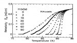
Measuring current without any resistance or voltage drop is actually pretty easy: If you know the dimensions of a superconducting magnet coild like those in an NMR machine, you only need to measure field strength to determine the circulating current in the coil.
This is somewhat comparable to measuring voltage using a voltmeter: The meter will put a tiny load on the magnetic field, just as a multimeter will always draw a minute amount of current from whatever voltage source you are measuring.
Also, the Ampere is a SI base unit, the Volt is not.