Welcome to Laser Pointer Forums - discuss green laser pointers, blue laser pointers, and all types of lasers

LPF Donation via Stripe | LPF Donation - Other Methods

Links below open in new window

ArcticMyst Security by Avery

Rethinking our approach to the DDL?

Joined
Jan 14, 2011
Messages
3,816
Points
63
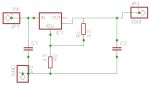
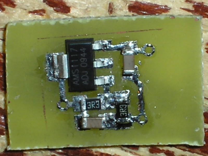
So I made up a circuit for a single LOC driven lm1117 (set to a voltage of about 2.5) so that there is some room for overhead. I am going to etch it today and try it out.


Joined
Jan 14, 2011
Messages
3,816
Points
63
Alright, so I am nearly finished with the board, etched and all. Just need to drill out the holes for leads (top right is Vin, top bottom right is GND [can be connected to either case pin or host], and bottom left is Vout). I designed this circuit specifically to run an LOC on a single battery using common pieces (1206 resistors and caps, LM1117 sot-223 IC).

Anyway, here is a picture of the nearly finished board.

P6050141.jpg


Pardon the incredibly crappy soldering job - I have really shaky hands. OH. And I forgot to use flux. Haha.

Anyway, I am going to go test it on my PSU and see how much current it delivers on a test-load with 4 1N4001s.

EDIT: Never mind. My soldering iron has already powered off and I don't want to power it back on.

Anyway, for anyone who wants the schematic and the board layout (made it as small as possible and doable on a single side [for easy home etching]), they will be attached as images. The actual files will be uploaded the MediaFire and can be found here:

.BRD file: lm1117 volt reg.brd
.SCH file: lm1117 volt reg.sch
 

Attachments

  • LM1117 volt reg board.png
    LM1117 volt reg board.png
    1.4 KB · Views: 1,045
  • LM1117 volt reg.png
    LM1117 volt reg.png
    3 KB · Views: 1,819
Last edited:
Joined
Oct 26, 2007
Messages
5,438
Points
83
Having said that, I totally disagree with you suggestion that any of us who can't building a BJT-Mosfet current sink shouldn't be in the laser making hobby to begin with. That's ridiculous. I can't build a BJT-Mosfet current sink. I shouldn't be in the laser hobby?

No, I said that if it is too complicated for someone to construct and analyze, they shouldn't be in the hobby (that link I posted explains it in a few lines).

I think I see what you're getting at now, trying to use the voltage regulator in a Kipkay fashion, only using the regulator instead of the battery as the reference voltage. Yeah that could probably work, but it will be hard to find easy to use voltage regulators that will have the right Vdo as well as some voltage margin at output to regulate current via a resistance. After a little searching, this regulator was about the best I could come up with. There were others, but they'd be harder to solder with. I think you could probably squeeze 100mV to play with below a 3.3V needed for a red diode. So it'd be 3.6-3.7V input, a 250mV Vdo, the voltage set to ~3.4V at the output so you have 50-100mV of voltage for current regulation via a resistor. If you could manage 100mV, you'd need a 0.3ohm resistor below your diode.
 

rhd

0
Joined
Dec 7, 2010
Messages
8,475
Points
0
I think I see what you're getting at now, trying to use the voltage regulator in a Kipkay fashion, only using the regulator instead of the battery as the reference voltage. Yeah that could probably work, but it will be hard to find easy to use voltage regulators that will have the right Vdo as well as some voltage margin at output to regulate current via a resistance.

Not quite what I was getting at no. I'm not suggesting that we simply take input voltage, minus Vdo, and look for a resulting A-B = desirable diode Vf.

Rather, I'm saying find the lowest dropout regulator we can. So, say 300mV (there are a few). Set it to provide an output voltage of whatever the LOC diode tends to use when consuming (say) 500mA current after a bit of warm up. If that value is 3.5V, then great, configure your circuit to provide 3.5V output (obviously you would need an adjustable positive LDO regulator, not a fixed voltage version).

Behind the scenes, you'd want to be conscious of what your margin was. IE, in the example above we required Vf of 3.5 + Vdo of 0.3 = 3.8V. So it would be desirable to keep your cell at above 3.8V. If it's 4V, that's still fine, the diode gets the same voltage/current. If it's 3.9V, fine. etc etc etc.

But no, I wasn't saying that we rely on the inherent supply limitations of the regulator, the way Kipkay might rely on the inherent voltage limitations of a battery to prevent over-current.
 

Benm

0
Joined
Aug 16, 2007
Messages
7,896
Points
113
Having said that, I totally disagree with you suggestion that any of us who can't building a BJT-Mosfet current sink shouldn't be in the laser making hobby to begin with. That's ridiculous. I can't build a BJT-Mosfet current sink. I shouldn't be in the laser hobby?

I am quite sure that anyone that can build a LM317 based driver can also build a 2 transistor or bjt-mosfet current sink or source. You may not be able to -design- one (yet), but building them is straightforward and only involves a few simple components.

I have drawn the basic 2 transistor sink here: Merghart.com - 2 Transistor current source

This example uses 2 bipolar transistors, but you you want to have an even lower voltage drop, you're welcome to replace T2 by a suitable mosfet. One important aspect is chosing the correct mosfet - you will need one with a relatively low Vgs threshold and low Rds within the voltage supplied by your batteries.

For circuits running for 2 lithiums in series this will not be a problem, but if you're trying to run a pump diode from 1 cell it will most likely be tricky to find a suitable mosfet.
 

rhd

0
Joined
Dec 7, 2010
Messages
8,475
Points
0
Hey,

Very neat post. I'm going to give that circuit a shot, and prove you all right. lol
I'll use a 1.1 ohm R2, to produce 545mA of current for an LPC 826 on one cell. If possible, count me very happy.

- How do I determine that wattage required for those resistors? Will 1/4 Watt be ok?

- When you talk about mirroring the circuit, I'm not familiar with the conventions engage in mirroring an electronics circuit. Taking a literal mirror image of the circuit doesn't seem to me like it would change anything about the circuit - so I must be unaware of what that term implies.
 
Joined
Sep 12, 2007
Messages
9,399
Points
113
"Q1 will ensure a constant voltage of 0.6 to 0.7 volts over Rset."

P=VI, so P=0.7*0.545 = 0.38W
 
Joined
Feb 9, 2011
Messages
578
Points
0
Wow, I just noticed this thread.

Sorry, for the lack of reading all the posts, but I just skimmed through it.

I actually tested the MIC29312 for a red LD and it's possible to run it with a single Lithium battery. However, the usual formula for calculating current doesn't hold true (I = 1.24/R)

I used 2 4.3 ohm resistors in parallel to give me 2.15 ohms, which should output 577mA but for a red it only outputs 287ma-255ma using a single 18650 unprotected.

I tried to make to make formulas for calculating this, but haven't been successful so far. Maybe if someone could whip out a formula for calculating required resistance this would eliminate the need to look for other ICs?
 

Benm

0
Joined
Aug 16, 2007
Messages
7,896
Points
113
Hey,

Very neat post. I'm going to give that circuit a shot, and prove you all right. lol
I'll use a 1.1 ohm R2, to produce 545mA of current for an LPC 826 on one cell. If possible, count me very happy.

- How do I determine that wattage required for those resistors? Will 1/4 Watt be ok?

- When you talk about mirroring the circuit, I'm not familiar with the conventions engage in mirroring an electronics circuit. Taking a literal mirror image of the circuit doesn't seem to me like it would change anything about the circuit - so I must be unaware of what that term implies.

See above for the resistor, you will need either a 0.5 watt 1.1 ohm, or you can use two 2.2 ohm, 0.25 watt resistors in paralel (or three 3.3 ohms if you have them around).

Mirroring the circuit involves replacing the NPN transistors with PNP transistors, and putting the transistors in the positive end of the circuit. Basically you can just flip the battery around, and leave the rest of the circuit entirely as it is - apart from flipping the diode around too obviously. The equivalent PNP replacements for the circuit as drawn are BC557 and BD140.

This circuit only requires 1.1 total voltage dropout, less than the reference voltage in the DDL circuit, and FAR less than the reference + dropout voltage as per the LM317 datasheet (4.25 volts!).
 

rhd

0
Joined
Dec 7, 2010
Messages
8,475
Points
0
This is really neat guys!

One Q - if the voltage was much higher than needed, which component would dissipate the bulk of the excess voltage as heat?

Also, I may also order a mosfet and gave that suggestion a try too. Knowing little about mosfets, does anyone know of an appropriate part number off hand?
 
Joined
Jan 14, 2011
Messages
3,816
Points
63
Yeah... I LIKE that. 1.1V drop out total? Sexy - that means we can give our reds ~3V, which is more than enough for high power (input current of about 380mA or so). And if we used an LPC-826... that's great! We can give those things 500mA at 3V.

Gonna draw up the circuit and the board on Eagle tonight... unfortunately, I have no fast access to cheap SMD transistors. Oh well. Maybe Fry's Electronics carries them....
 
Joined
Sep 20, 2008
Messages
17,622
Points
113
This is really neat guys!

One Q - if the voltage was much higher than needed, which component would dissipate the bulk of the excess voltage as heat?

Also, I may also order a mosfet and gave that suggestion a try too. Knowing little about mosfets, does anyone know of an appropriate part number off hand?

I find it strange that you quote all kinds of electronic criteria
at the beginning of this thread about what you would like to
achieve but I get the feeling that you are not as sure of what
specifications of parts you are looking for....

It seem that you want the members of LPF to come up with a
viable Ultra Low Dropout Linear Voltage Regulator circuit design
for you....

I may be mistaken but when I see a question like "does anyone
know of an appropriate part number off hand?"....that seems to
me a lack of knowledge of what is required...
Data sheets a Free... all we need to do is read them....

Sorry if this sounds off but that's the felling I get from reading
this thread...:undecided:
I'm not trying to offend anyone....:beer:


Jerry
 
Last edited:

Benm

0
Joined
Aug 16, 2007
Messages
7,896
Points
113
This is really neat guys!

One Q - if the voltage was much higher than needed, which component would dissipate the bulk of the excess voltage as heat?

The BD139 takes all the excess power, apart from what is wasted in the sense resistors. It may require heatsinking in some applications, particularly when diving bluray or 445 diodes at high currents from voltage sources that supply more than you need.

The power calculations are in the writeup, including some examples.
 
  • Like
Reactions: rhd
Joined
Sep 12, 2007
Messages
9,399
Points
113
I actually tested the MIC29312 for a red LD and it's possible to run it with a single Lithium battery. However, the usual formula for calculating current doesn't hold true...should output 577mA but for a red it only outputs 287ma-255ma

That might be because you're not giving it enough voltage. Try two lithiums, and you'll likely get more current.
 
Joined
Feb 9, 2011
Messages
578
Points
0
That was on purpose, I wanted to use one battery. It was outputting 255mA at 4.03V and I think 287mA at 4.15V.
 

rhd

0
Joined
Dec 7, 2010
Messages
8,475
Points
0
Yeah... I LIKE that. 1.1V drop out total? Sexy - that means we can give our reds ~3V, which is more than enough for high power (input current of about 380mA or so). And if we used an LPC-826... that's great! We can give those things 500mA at 3V.

I'm not totally convinced on that front Wolfman. I've seen some conflicting PIV charts, but at 500mA, I'm almost certain a LOC will need more than 3V. My sense from that recent 826 testing that was commission, is that they might be slightly lower on the voltage front - or perhaps the original PIV curves that we've been looking at for 815 LOC's all this time, have been wrong.

I find it strange that you quote all kinds of electronic criteria at the beginning of this thread about what you would like to achieve but I get the feeling that you are not as sure of what specifications of parts you are looking for....

Really?
Why do you find that strange?
I find that normal.

That concept is fairly fundamental to how groups of people, and society in general, function. Someone wants to achieve something and doesn't know how to, or can't on their own. So they ask others, and work together to achieve their goal. It's rewarding. I recommend you give it a shot ;)

It seem that you want the members of LPF to come up with a viable Ultra Low Dropout Linear Voltage Regulator circuit design for you....

If I wanted them to do it for me, I'd just wait. It will happen. Technology constantly evolves. It doesn't need my threads in order to do so ;)

I'd just like to be a part of the discussion, and chip in with what I can. Ideas come to me and sometimes they're good, sometimes they're bad. But when it comes to electronics, what they almost ALWAYS are is a little bit beyond my actual skillset & expertise. I'm not an electronics major (if you knew what I'm doing my grad studies in, you'd laugh). So I bounce the ideas off other people here who have more extensive practical knowledge.

I may be mistaken but when I see a question like "does anyone know of an appropriate part number off hand?"....that seems to me a lack of knowledge of what is required... Data sheets a Free... all we need to do is read them....

It is a lack of knowledge. But isn't that exactly what I said in my post? That I have "little knowledge of mosfets"? Good detective work ;)

Not to dissuade anyone from reading, but there's such a thing as unnecessary reading. If there's a common part number that someone can reply with in 8 characters, so that I can order it now, and then figure it out in three weeks when it actually arrives from China and I have more time, why would it be so offensive to you that I ask for this courtesy instead of spending 30 minutes on digikey reading datasheets now?

Sorry if this sounds off but that's the felling I get from reading
this thread...:undecided:
I'm not trying to offend anyone....:beer:
Jerry

Well Jerry, you are trying to offend someone. Saying that you're not, at the end of your thread, doesn't change the contents of what you've actually said.

If we're going to be honest here, I can't really remember the last time that I've read a thread where I left feeling as though YOU had contributed something positive to the dialogue or debate.

I think I come at this board with good intentions, and an ambition to try new things. Quite often, that requires help from other people. I've always done as much as possible to payback that help both directly to the individual, and indirectly to the board and other users in general.

I cannot say that I get the same impression from you. I rarely observe you doing anything positive, or encouraging free open discussion. I all the more often observe you trying to shut down ideas, and maintain the status quo. What is it about this forum that attracts you Jerry? You've certainly been here a lot longer than I. I don't get it.
 
Last edited:


Top