Welcome to Laser Pointer Forums - discuss green laser pointers, blue laser pointers, and all types of lasers

LPF Donation via Stripe | LPF Donation - Other Methods

Links below open in new window

ArcticMyst Security by Avery

Question about PC PSU

LaZeRz

0
Joined
Feb 19, 2011
Messages
2,549
Points
63
Re: Question about PC PS

I've also read that the 3.3V rail and the 5V rail also shares a common power output, does this mean if I load either the 12V, 5V or 3.3V rail, all of them will be loaded properly?

@Lazerz Looks great, do you think there is a possibility that I would be able to fit all the regulating circuitry inside the PSU's box?

Its possible but not worth it in my opinion, project box would be much easier to work with.

Also, I wouldn't recommend using a linear regulator if you're going to be using a low voltage. Lot of heat. When I hooked up a supercap (2.7v) to it, in about 10 minutes the whole heatsink was way too hot to touch.

I'd build a separate circuit on the 5v line if you need it for low voltage applications.


Joined
Jul 22, 2012
Messages
426
Points
28
Thanks Lazerz for the advice, I'll incorporate that into my circuit.

Sorry, I have got more questions :eek: :
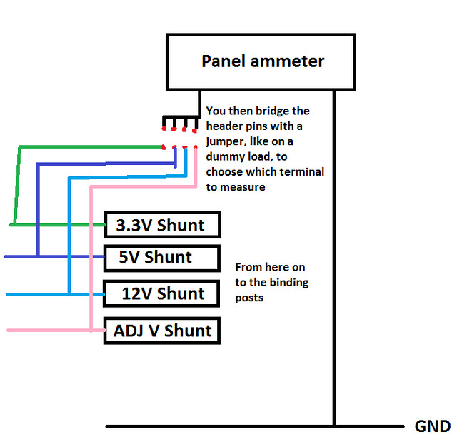
1) I want to be able to measure the current on the PSU going through each of the binding posts, and the only way I found that could measure the current without the current literally going through the ammeter (I don't want this as it would just make more problems), is using a panel ammeter with a shunt. Let the crappy schematic do the talking:

8958203602_9d083150d4_z.jpg


Any other way to do this without using all that shunts?

2)I would like to add a variable constant current setting, but whenever I use a circuit we use for a DDL driver with a LM317 or LM338, the current jumps with a miniscule turn of the pot. Any other high constant current (>5A) circuit you know about? I couldn't find any.

EDIT: Can you guys see the pic? I can't, I would like to know if the fault is on my side.
 
Last edited:

LaZeRz

0
Joined
Feb 19, 2011
Messages
2,549
Points
63
I only have adj voltage so not too sure about that. You might need a multiturn pot.

Can't see the pic, how did you upload it?
 

honeyx

0
Joined
Jun 12, 2011
Messages
377
Points
28
Yes, a multiturn 5W 200Ohm pot in series with a 0.25 Ohm 5W shunt resistor should be fine.
 
Joined
Jul 22, 2012
Messages
426
Points
28
I copied the wrong image url :banghead: But just using a pot isn't CC and even though I've used a precision multi-turn pot in the past, it still did the same.
 
Last edited:

honeyx

0
Joined
Jun 12, 2011
Messages
377
Points
28
So how about adding a secound 1 or 10k Ohm pot in parallel for fine tunning?

In this case you would have to limit its resistance by adding a resistor in series to the secound pot. Both ends attached in parallel to the main multiturn pot.
 
Last edited:
Joined
Jul 22, 2012
Messages
426
Points
28
Also, the pots are usually not a high enough wattage. When using a circuit with something like a LM317 the current flows through the resistor across the ADJ and OUT pin if I'm not mistaken, so doing 3A at 5V with that pot is not going to last long.
 

honeyx

0
Joined
Jun 12, 2011
Messages
377
Points
28
That´s why I suggested to use a big 5W multiturn pot together with a 0,25 Ohm 5W shunt resistor in series. Together you will have a 10W resistor and the voltage between ADJ and OUT will always ramain the same, which is 1,25V but not 5V. So just to be on the safe side, you can take 10W for both.
 
Joined
Jul 22, 2012
Messages
426
Points
28
Oohh, sorry, I misunderstood you. But isn't what you said (About the wattages of the resistor adding up) only true for when you connect resistors in parallel? Like when you put 2 X 2E 10W resistors in parallel, to give a 20W 1E resistor (because each resistor will be able to dissipate 10W on its own)?
 

honeyx

0
Joined
Jun 12, 2011
Messages
377
Points
28
It´s legit for both. Using in parallel and serial. Wattage is always U*I. So lets say you are feeding a 1Ohm resistor with 1A at 5V. This will result in 5W for the resistor. Now let´s say you are feeding two 1 ohm resistors in series at 5V with 1 A. This will result in 1 A passing both but the voltage being devided between both, so you will get 2,5V at each. The total consumption will be still the same, but each resistor will consume just 2,5W.
 
Joined
Jul 22, 2012
Messages
426
Points
28
Sorry for my ignorance, but I noticed this:

Let's say you have a 1E at 5V and, running at 5A, the resistor will be dissipating 25W. Running two 0.5E resistors in series, will mean that each resistor will only be dissipating 12.5W. Here that works correctly.

But if you use a pot of 10E and a shunt resistor of 0.25E, running at 10V, the results would be as follow:

The pot: (10(V)/10.25(Total resistance))*10(Resistance of pot)=9.75V over the pot, meaning 9.5W being dissipated by the pot.

The shunt: (10(V)/10.25(Total resistance))*0.25(Resistance of shunt)= 0.243V over the shunt, meaning only 0.237W being dissipated by the shunt.

This means it does not work like you predicted it would, is my calculations correct? I don't think your rule works for all resistance combinations.
 

honeyx

0
Joined
Jun 12, 2011
Messages
377
Points
28
I think you should study a bit more about LM317 and LM 338 regulators. The voltage between ADJ and OUT remains always the same, which is 1,25V. So to calculate the wattage over the resistors you have to use this voltage. So lets say the 200 Ohm pot is turned to be 200 Ohm. Together with the shunt resistor this results in 200,25 Ohm.

1,25v/ 200,25Ohm =0,006A
0,006A*1,25V = 0,0075W total

Now turning the pot to 1 ohm, which results in 1,25 Ohm.

1,25V / 1,25 ohm = 1A

1A*1,25V = 1,25W

and finally turning the pot to 0

there you have only the resistance of the shunt resistor.

1,25V / 0,25 ohm = 5A

5A* 1,25V = 6,25 W

So in real you just would need about a 2W pot and lets better say a 7W shunt resistor, though a 5W could do it too with some extra passive cooling.

You can also take 4x 1 Ohm 2,5W resistors in parallel to build the shunt resistor, which would result in 0,25 ohm 10W.
 
Last edited:
Joined
Jul 22, 2012
Messages
426
Points
28
Ok, thanks for explaining :thanks: I'm still learning about electronics as I'm sure you noticed (Although I know the voltage across the ADJ and OUT pins are only 1.25V, previous post was just an example) :) So is there any other way to measure the current like I described above without all that shunts?
 
Joined
Sep 12, 2007
Messages
9,399
Points
113
So lets say you are feeding a 1Ohm resistor with 1A at 5V. This will result in 5W for the resistor.

That's not possible. You can't just ignore ohm's law. 5V on 1Ω is 5A and 25W dissipated on the resistor.

Now let´s say you are feeding two 1 ohm resistors in series at 5V with 1 A. This will result in 1 A passing both

No, because that's 2Ω. 5V on 2Ω is 2.5A on each resistor, and 2.5V on each resistor for a total of 6.25W on each.

I also told you in the past I´m not german, though I´m living there. So belive in what you want, even in witches.

EwPkP.jpg


Where did THAT come from? Who said anything about your nationality? What does German witchcraft have to do with PC power supplies?
 
Joined
Dec 23, 2008
Messages
3,948
Points
63
the shamwow is made in Germany, although I see no direct correlation

Michael.
 

honeyx

0
Joined
Jun 12, 2011
Messages
377
Points
28
That's not possible. You can't just ignore ohm's law. 5V on 1Ω is 5A and 25W dissipated on the resistor.
You are right and I´m not ignoring ogm´s law, just gave this as an simple example for better understanding. This is just hypothetical what you would get by feeding the resistor with a constant voltage and constant current source.

But regarding ohm´s law you are of course right.

No, because that's 2Ω. 5V on 2Ω is 2.5A on each resistor, and 2.5V on each resistor for a total of 6.25W on each.

Here you are also right. That´s what you really get, but like said it was just used as an example for better understanding why it´s legit for using resistors in parallel and serial.

Ok, thanks for explaining :thanks: I'm still learning about electronics as I'm sure you noticed (Although I know the voltage across the ADJ and OUT pins are only 1.25V, previous post was just an example) :)

No problem :) I think now it´s cleared which were just pure examples :)

So is there any other way to measure the current like I described above without all that shunts?

Hmmm. I think best would be to use a 0.1 ohm or 0.01 ohm shunt resistor between the PSU and the LM338 and an op-Amp to measure the current.

So the whole aparature would look about like this.

PSU - 0.01 shunt - LM338(constant current with pot and shunt) - LM338 (constant voltage + adj. pot) - output
............Op-Amp...................................................................Panel (Voltage)
..........Panel (current)
 
Last edited:


Top