Welcome to Laser Pointer Forums - discuss green laser pointers, blue laser pointers, and all types of lasers

LPF Donation via Stripe | LPF Donation - Other Methods

Links below open in new window

ArcticMyst Security by Avery

Putting a Flexmod P3 behind an X-Drive

vk2fro

0
Joined
Nov 30, 2009
Messages
1,304
Points
63
Gday folks

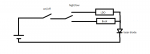
Recently I got one of DTR's great 520nm diodes with a X-Drive behind it (pushing 1.8A). If I power this thing its straight up full power. What I need to do is have a low power aiming beam, then be able to switch to full power after putting my goggles on.

My thoughts were (considering I have a spare flexmod) was to put the flexmod behind the X-Drive, set the idle current to just above the current required to get a low power aiming beam, and the max current to whatever gives the most power out of the module). I havent measured what full power draw is at 7.4 volts, as I dont have my saftey glasses yet (dont trust my wicked laser set, so have some ARG 33's coming from NOIR).

The whole purpose of this is so that I can use the module as a laser engraver with a foot pedal. The other option would be to simply build a two stage supply using LM317's to control the output current (or LM338's from memory for more amps).

I've fired the unit on my variable voltage current limited supply, and found it's threshold current. So would the flexmod have a fit if it was driving a driver instead of a diode?

Thanks for any input.


anderp

0
Joined
May 17, 2015
Messages
27
Points
3
You'd probably want to put in a filtering cap between them, but I can't see why it wouldn't work - they're not switchmode, so the usual shenanigans with daisychaining switchmode supplies won't apply.

Why not just use the modulation input of the flexmod, and power the diode directly from the flexmod, though? it's simple enough to wire the pedal to output say 0.5v (adjustable with a trimmer) when your foot is off it and 5v (max power) when the switch is pressed. The manual seems to imply that it doesn't PWM, so there should be no issue with looking at a lower power beam?
 
Last edited:
Joined
Sep 12, 2007
Messages
9,399
Points
113
That's expensive, larger than necessary, impractical, and possibly hard on the switching driver. Use something smaller like a LDO for the low current, and use a DPST to switch between main driver and aiming driver.
 

vk2fro

0
Joined
Nov 30, 2009
Messages
1,304
Points
63
I don't like the idea of a switch in the lasers supply (well physically). I don't want to introduce spikes. The whole idea of this is coz I already have the bits at hand. No one wants to take chances with a $370 (AU $500) diode :)
 

vk2fro

0
Joined
Nov 30, 2009
Messages
1,304
Points
63
Totally understand you cyp - cept what I need is an aiming beam - the switch would turn the laser off altogether hence using low current (0V modulation) to have the diode just barely lasing, then punch up to etching power when the switch is closed :)..

I'll draw a schematic later and post it up - :)
 
Joined
Sep 12, 2007
Messages
9,399
Points
113
Totally understand you cyp

No, you don't. Not even in the slightest. Here, maybe this will help.

attachment.php
 

Attachments

  • hilow.png
    hilow.png
    4.6 KB · Views: 238
Last edited:

anderp

0
Joined
May 17, 2015
Messages
27
Points
3
Guys, the flexmod P3 has this functionality already built in with its modulation input!

Noisy contacts switching power between two drivers are completely un-neccessary. You just set the flexmod's maximum current to 1.8 amps, minimum (0 Bias pot) to just barely enough to let the diode lase, remove the X-Drive entirely, and use the modulation input on the flexmod. Your footswitch connects the modulation line to +5v, with a pull-down resistor to hold it at 0v when the switch is off. For added flexibility, the switch could swap in/out a potentiometer instead of +5v, and you've got adjustability for the high-power mode.

Done. No stacking switches, no messy driver changes to alter power levels.

occam's razor; the simplest solution is usually the correct one, and one driver is definitely simpler than two :p
 
Last edited:
Joined
Sep 12, 2007
Messages
9,399
Points
113
Noisy contacts switching power between two drivers are completely un-neccessary.

All pointers have "noisy contacts", and this is irrelevant because the drivers will filter this out. I'll remind you they are constant current.

You try building a device without any switches and tell me how it goes.

Your footswitch connects the modulation line to +5v, with a pull-down resistor to hold it at 0v when the switch is off. For added flexibility, the switch could swap in/out a potentiometer

Funny how you complain about the "noise" in switches, then you add switches and pots.

Guys, the flexmod P3 has this functionality already built in with its modulation input!

Yes, but it's a linear device, and therefore far less efficient than a buck regulator.

occam's razor; the simplest solution is usually the correct one

LM317 is the simplest solution. That doesn't necessarily make it the correct one. Engineering has more to it than occam's razor.


Top