Welcome to Laser Pointer Forums - discuss green laser pointers, blue laser pointers, and all types of lasers

Buy Site Supporter Role (remove some ads) | LPF Donations

Links below open in new window

FrozenGate by Avery

Please help with PT4115 driver for 445nm 1W

Berni

0
Joined
Sep 9, 2010
Messages
41
Points
0
Hi,

Recently, I got a 445nm laser 1W from lvyilaser.
I read on laser reviews board that the driver don't reach 1W but 500/700mw
Standart specification for pt4115 is max 1.2W with DC 8-30v .

Link : http://www.micro-bridge.com/data/CRpowtech/PT4115E.pdf

I try to understand why the driver don't reach 1W . To change DC in from 6.2v to 8v do nothing, dc led is the same.
I looking the layout of lyvilaser driver and saw that 47μH placed differently !
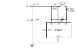
Please take a look to layout of lvyilaser and standart layout for power led.


STANDART LED APPLICATION
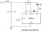
PT4115start.jpg

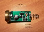
LVYILASER DRIVER
Driver lvyi.jpg

Thanks for your help.
Bernard
 
Last edited:


Modification lvyi driver for 1W

Hi,

Finally I find how to modifie 445nm lvyilaser Driver to reach 1W.
The driver design seem to be good, but remplacement 2 components will give more current to the Led (more power)..
1 - Replace L = 47uH with 27uH
2 - Replace Rcs=0.102ohm (5 resistances 0.51ohm weld in parallel) with Rcs=0.0825ohm (4 resistances 0.33ohm weld in parallel).

Information : http://www.micro-bridge.com/data/CRpowtech/PT4115E.pdf

driver.JPGIw.JPGL1000891.jpg
 
Last edited:
Hi Berni, where do you get the parts?
Was that very hard to get out of the tube!

Mine burns well, I wish I had a meter to see how strong it is. I have killed 2 wasps and 6 spiders with it , so far.:beer:

Jeff
 
Last edited:
PT4115 is a standard LED driver, step-down only, and the resistor that you have changed is used from the internal comparator for set up the current ..... careful to not go under a certain value, otherwise you will burn it.

Also, considerate that, in the normal use, it's planned for take from 8 to 30V, where instead in the use with 2 Li-Ion batteries, it's usually powered at 7,2 / 7,4V, and this, other than the fact that is underpowered, means also that for give you the same output current, it need to use more current from the batteries (and the efficency is lower, too, and also, the working cycle can be unstable for high currents) ..... this basically also means that an inductance with a more high current saturation threshold works better than one with lower one, at the same inductance values ..... probably, your 27uH one have a higher saturation value, so it work better also if the value is less than the suggested one.

BTW, current saturation, for inductances, is a different thing from maximum current that the wire can hold ..... said in poor words, it's the maximum current that you can pump in it, totally saturating the magnetic core, where over that value, more current DON'T cause more magnetic energy accumulation ..... and, cause these power supplies uses this magnetic energy accumulation for re-convert it in output power, is easy to understand that you can get more power, if the stored energy for each cycle is higher ..... probably, if you can get a 47uH inductance with a better current saturation level, you can take from the driver also more current.
 
Hi Berni, where do you get the parts?
Was that very hard to get out of the tube!

Mine burns well, I wish I had a meter to see how strong it is. I have killed 2 wasps and 6 spiders with it , so far.:beer:

Jeff

Hi Jeff,

Picture is best for understand >>>>

L1000892.jpg L1000893.jpg

Easy to unscrew with a metal pincette.

Bernard
 
links are dead for me :( I'm sooo interested in this IC :(
 
Last edited:
PT4115 is a standard LED driver, step-down only, and the resistor that you have changed is used from the internal comparator for set up the current ..... careful to not go under a certain value, otherwise you will burn it.

Also, considerate that, in the normal use, it's planned for take from 8 to 30V, where instead in the use with 2 Li-Ion batteries, it's usually powered at 7,2 / 7,4V, and this, other than the fact that is underpowered, means also that for give you the same output current, it need to use more current from the batteries (and the efficency is lower, too, and also, the working cycle can be unstable for high currents) ..... this basically also means that an inductance with a more high current saturation threshold works better than one with lower one, at the same inductance values ..... probably, your 27uH one have a higher saturation value, so it work better also if the value is less than the suggested one.

BTW, current saturation, for inductances, is a different thing from maximum current that the wire can hold ..... said in poor words, it's the maximum current that you can pump in it, totally saturating the magnetic core, where over that value, more current DON'T cause more magnetic energy accumulation ..... and, cause these power supplies uses this magnetic energy accumulation for re-convert it in output power, is easy to understand that you can get more power, if the stored energy for each cycle is higher ..... probably, if you can get a 47uH inductance with a better current saturation level, you can take from the driver also more current.

Of course PT4115 is planned for take from 8V but it also work for me (and other) with 7.2/7.4V battery that give 700/750 mW laser Output (lasersbee review).
Unfortunately Lvyilaser has planed his driver with standart middle values that give less current (700/750mA) to the Led.
But if you look at the PowerTech PT4115 data you will see that there is another configuration for high current output.

All given informations about the driver modification are from the conceptor of the PT4115 CI (PowTech). please take a look at >>

http://www.micro-bridge.com/data/CRpowtech/PT4115E.pdf

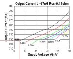
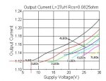
With middle value like on the lvyilaser driver L= 47uH, Rcs=0.13Ω (lvyi = 0.101Ω = 5x 0.51Ω prallel) , the output current with 1 Diode IS around 720mA with 7.5V battery

Find on PowerTech pt4115 data : Graphe 47.JPG

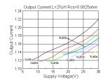
But if you change for L= 27uH and Rcs=0.0825ohm (4X 0.33Ω prallel), your output current with 1 Diode will be more than 1100mA with 7.5V battery

Find on PowerTech pt4115 data : Iw.JPG

P.S. I haven't tried yet this modification, 27uH and 4 x 0.33Ω CMS are waiting for shipping
.

A+
Bernard
 
Yes, i have this datasheet too, but remember one thing, doing your experiments ..... they give you the graphics, speaking about LEDs, not about laser diodes, and laser diodes have different forward voltages than LEDs ..... (in a standard switching regulator this don't influence the frequency, unfortunately this chip, for simplicity, was made as "free-running" variable oscillator, and the working frequency can change from load voltage, load current, temperature ..... (from 100KHz to almost 1 MHz, in fact, is A LOT of change :p)

Speaking about "power leds", usually 1W or 3W white ones, they have a typical FV of 3,3 to 3,6V, where instead a 445nm LD have a typical FV of 4,5 / 4,7V ..... so, in the graphic that they give you, you must consider the LD as an "one led and half" load, approximatively ..... not needing lab precision, you can ideally track a curve between the 1-led and 2-led ones, and use that for see the resulting values ..... anyway i think is still possible, from these graphics, to reach at least 1A output (also if unstable), with that configuration (and the 27uH, that must place the working frequency around 100 / 150 KHz), with 7,2 / 7,4V ..... cannot speak about more-than-1A, anyway, especially if the voltage go under 7V .....
 
It's from a 1W 445nm lvyilaser.

1W 445nm Blue laser pointer , $170.00 - 1w.1000mW .445nm blue laser pointer,1W 445nm laser pointer,445nm blue laser.1w 445nm laser pointer.1000mW 445nm laser.

I am very satisfed with this laser. The price of 170 dollars includes:a 1W 445nm blue laser pointer,(two cr123a battery),a pair of laser glasses, a CR123A charger and includes the shipping fee(DHL.UPS.FedEx.TNT.EMS).

Bernard

I agree, I like mine also! I don't have an lpm, but I like it and have not had any problems.

Thanks for the pics Berni!

Jeff


Back
Top