

- Joined
- Dec 27, 2011
- Messages
- 2,062
- Points
- 48
When putting together a parts list for the Benboost, I found what I thought was the holy grail of 0805 capacitors. It was a Kemet x7r, 22uF, 16v 0805 capacitor from Allied Electronics.
It was on sale and seemed to be the perfect capacitor for output on many drivers, especially the BenBoost.
In fact, at one point there was some question about whether Benboots were killing 12x 405's and single mode blue diodes.
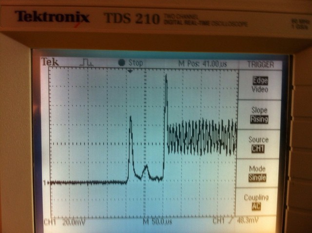
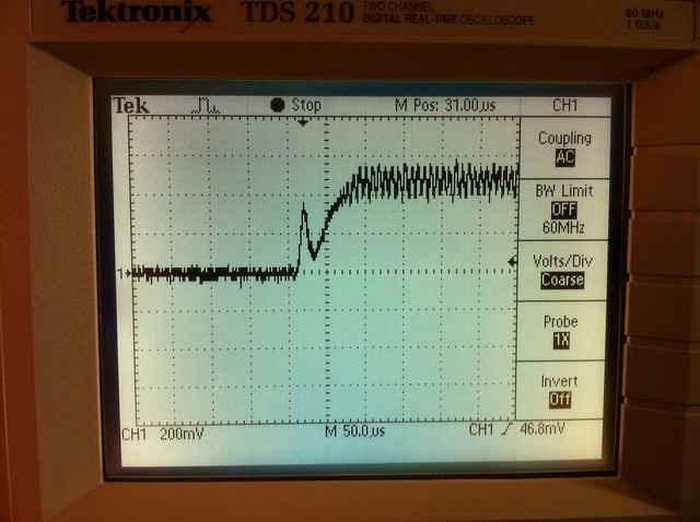
So, I took a Moh version of the Benboost, with 10uF capacitors on it and tested it on a scope, then wiped them and installed the Kemet 22uF caps and saw a great improvement.
Meanwhile, LeQuack built a 405 using parts for the Benboost including the 22uF Kemet capacitors from Allied Electronics.
Recently Foumist (Tom) asked to buy some driver parts from me. I threw some of these caps in with the package as a gift.
Tom wrote me today to earn me that he tested them and they were only 2.2uF? I doubted this, since I had ordered them from a reputable supplier, but I tested them myself and got 2.2uF as well.
I contacted LeQuack and he did some research and the short version is that Allied missed by a decimal point. They did this on TWO versions of the capacitor. A 20% and 10% version were both listed as 22uF, 16v x7r caps. In reality, they are 2.2uF, 16v, x7r caps. All of them, even though they are two different part numbers and two different tolerances. Allied screwed up... And I did not think to check them...
Now, here is where it REALLY gets weird.
First, LeQuack has been using these without problem in his 405nm 12x build.
Second, I recently tested the Benboosts and they did better with the 2.2uF caps than with the 10uF caps on output.
Third, LeQuack tested them on a different driver as well. They performed BETTER than the 10uF caps on this driver as well.
He did some asking on other sites and it has been suggested that since we are designing constant current drivers based off of constant voltage chips and schematics, maybe the higher capacitance is slowing the ripple frequency (which would explain the slower than expected frequency on the benboost) and creating more heat.
I wanted to put this out there, I don't know who I have sent all these parts to, but if you have caps from me, they may be incorrect,
Also, they may work! We are trying to figure out why this is happening.
I am wide open to discussions...
It was on sale and seemed to be the perfect capacitor for output on many drivers, especially the BenBoost.
In fact, at one point there was some question about whether Benboots were killing 12x 405's and single mode blue diodes.
So, I took a Moh version of the Benboost, with 10uF capacitors on it and tested it on a scope, then wiped them and installed the Kemet 22uF caps and saw a great improvement.
Meanwhile, LeQuack built a 405 using parts for the Benboost including the 22uF Kemet capacitors from Allied Electronics.
Recently Foumist (Tom) asked to buy some driver parts from me. I threw some of these caps in with the package as a gift.
Tom wrote me today to earn me that he tested them and they were only 2.2uF? I doubted this, since I had ordered them from a reputable supplier, but I tested them myself and got 2.2uF as well.
I contacted LeQuack and he did some research and the short version is that Allied missed by a decimal point. They did this on TWO versions of the capacitor. A 20% and 10% version were both listed as 22uF, 16v x7r caps. In reality, they are 2.2uF, 16v, x7r caps. All of them, even though they are two different part numbers and two different tolerances. Allied screwed up... And I did not think to check them...
Now, here is where it REALLY gets weird.
First, LeQuack has been using these without problem in his 405nm 12x build.
Second, I recently tested the Benboosts and they did better with the 2.2uF caps than with the 10uF caps on output.
Third, LeQuack tested them on a different driver as well. They performed BETTER than the 10uF caps on this driver as well.
He did some asking on other sites and it has been suggested that since we are designing constant current drivers based off of constant voltage chips and schematics, maybe the higher capacitance is slowing the ripple frequency (which would explain the slower than expected frequency on the benboost) and creating more heat.
I wanted to put this out there, I don't know who I have sent all these parts to, but if you have caps from me, they may be incorrect,
Also, they may work! We are trying to figure out why this is happening.
I am wide open to discussions...
Last edited:


")