Welcome to Laser Pointer Forums - discuss green laser pointers, blue laser pointers, and all types of lasers

LPF Donation via Stripe | LPF Donation - Other Methods

Links below open in new window

ArcticMyst Security by Avery

OPEN SOURCE: The "Heavy Load" - REALLY high current (10 Amp) test load

IWIRE

0
Joined
Dec 18, 2013
Messages
630
Points
0
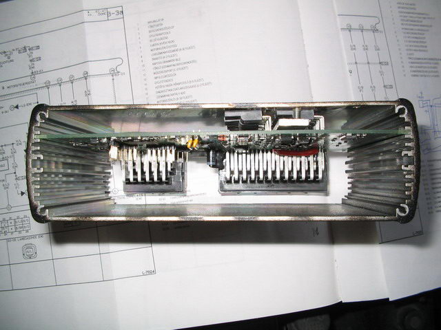
Just got a chance to test the load out. It works great ! I've been pumping 4.4a in it, I haven't tried doing it for 5 min. yet. I want to get a fan blowing across it before I try that. I'm going to look at the spec sheet for the diode, see what max temp is and shoot this thing with my IR thermometer. I have a hard time telling by touch.
I'm impressed. Looking forward to the revised model.


rhd

0
Joined
Dec 7, 2010
Messages
8,475
Points
0
What do you guys think of flipping around one row of the diodes so that they both face in, and could be attached to opposite sides of the same piece of aluminum?
 
Joined
Jul 4, 2012
Messages
2,834
Points
63
I would like to be able to see the chart though, wouldn't having one heatsink get in the way of it?
 

djQUAN

0
Joined
May 27, 2013
Messages
1,154
Points
63
You guys should try mounting the diodes and resistors underneath the PCB with the leads bent upwards and the PCB mounted above the devices. With a heatsink/plate with atleast one flat side would allow you to have unlimited heatsink size.

Bat_Cycle_Mech_Assy.gif


1adZt.jpg


002.jpg


Edit: I can help in the PCB design regarding arranging the parts for optimum placement if you'd like. I'm not expecting any in return just want to help :)
 
Last edited:

rhd

0
Joined
Dec 7, 2010
Messages
8,475
Points
0
Let me post the existing schematic and board files....
 

djQUAN

0
Joined
May 27, 2013
Messages
1,154
Points
63
It's almost 2am here right now so I probably might not be able to work on it until tomorrow. Just letting you guys know :)
 

IWIRE

0
Joined
Dec 18, 2013
Messages
630
Points
0
What do you guys think of flipping around one row of the diodes so that they both face in, and could be attached to opposite sides of the same piece of aluminum?

I was thinking the same thing. If there was an inch between them I could use a piece of 1" square aluminum tubing with with a CPU fan mounted at each end for airflow. :)
I'm really liking how consistent my current readings are staying . :beer:
 
Joined
Jul 4, 2012
Messages
2,834
Points
63
I was thinking the same thing. If there was an inch between them I could use a piece of 1" square aluminum tubing with with a CPU fan mounted at each end for airflow. :)
I'm really liking how consistent my current readings are staying . :beer:

that's a good idea. Especially if you could finagle it so there is 1 inch spacing, RHD. Although i highly doubt a heatsink AND a fan is necessary, would still be kinda cool. Although at that point its turning more into something that should be mounted somewhere than something you can pull out and use, then stick it back in a small drawer or box.
 

IWIRE

0
Joined
Dec 18, 2013
Messages
630
Points
0
Your right, most people wouldn't need a fan. It would be nice if there was room to do that I think.
This has gone from ordering some boards to rhd redesigning a test load.
I'm just thankful for the original style, now I can actually get a good test at the right voltage and my current stays consistent longer.

Here's an action shot :) 4.5a no smoke :)

 
Last edited:
Joined
Jul 4, 2012
Messages
2,834
Points
63
Alright, whats happening with this? Do you have an updated pcb design for us, RHD?

Oh another question I keep forgetting to ask, is the resistor even necessary? Couldnt you just measure accross a diode?
 
Last edited:

rhd

0
Joined
Dec 7, 2010
Messages
8,475
Points
0
Alright, whats happening with this? Do you have an updated pcb design for us, RHD?

Oh another question I keep forgetting to ask, is the resistor even necessary? Couldnt you just measure accross a diode?

No, haven't had time to yet.

And nope, because a diode doesn't have a linear and predictable current/voltage relationship like a resistor has. That's why there's a table for diode voltage drops, rather than a simple multiplier. You'll see that the Vdrop of 10A isn't 10x the Vdrop of 1A.

If you're using your DMM in current mode, then you don't need the resistor. BUT, using a DMM in current mode isn't a great idea with 10A of current.
 
Joined
Jul 4, 2012
Messages
2,834
Points
63
Ah, ok. Thanms for explaining. And I forgot about the ammeter mode. And im not trying to rush you by any means :) I dont think IWIRE is in any rush, and I certainly am not. I think I will wait until I get my reflow station to do both these and your boost drives.
 

IWIRE

0
Joined
Dec 18, 2013
Messages
630
Points
0
I was wanting to have a little volt meter and ammeter display permanently connected to mine. I'm having trouble finding an ammeter that does 10a without an external shunt. Think I will just put some pins on the board so I can take a current reading if I want to.

I've ran this load at 4.4a quite a bit and it is holding up great. I just shoot it with my IR thermometer and shut it down to cool when it hits 90°C.

If you want to order some of the black V2 boards let me know. I'd like to try it out also. I don't know how to order them in black or I would have them on the way. :beer:
 

djQUAN

0
Joined
May 27, 2013
Messages
1,154
Points
63
I think we're going to need a better jumper/selector switch than a pinheader if you plan to use it at 10A.
 

rhd

0
Joined
Dec 7, 2010
Messages
8,475
Points
0
I was wanting to have a little volt meter and ammeter display permanently connected to mine. I'm having trouble finding an ammeter that does 10a without an external shunt. Think I will just put some pins on the board so I can take a current reading if I want to.

I recently came across this dilemma for another project, and there's an easy solution... mimic the shunt with a resistor. That's all it is really.

If the ammeter calls for a 100A 75mV shunt, then you just use Ohm's law and backtrack to the resistance. In this case, it would be a 0.00075 ohm resistor that can handle 7.5 watts.

You could use 4x of RHM.003AUCT-ND in parallel

I think we're going to need a better jumper/selector switch than a pinheader if you plan to use it at 10A.

That would be worth switching as well, while we're at it. Better jumper ideas anyone?
 

djQUAN

0
Joined
May 27, 2013
Messages
1,154
Points
63
If the ammeter calls for a 100A 75mV shunt, then you just use Ohm's law and backtrack to the resistance. In this case, it would be a 0.00075 ohm resistor that can handle 7.5 watts.

You could use 4x of RHM.003AUCT-ND in parallel

That would work in an ideal world but at those low impedances, you're going to get much more PCB trace resistance than the shunt resistance. If the meter has a calibration pot, then it would be fine but you might need a lower value resistor than you think due to parasitic resistance of the trace. Then you'll definitely need kelvin sense connections for the sense lines.

As for the jumpers, I have no idea here at the moment. I'll post if I come across a good one.


Top