benmwv
0
- Joined
- Sep 10, 2010
- Messages
- 1,380
- Points
- 48
Sup guys, got another open source driver here!
When the pl520 green diodes came out I had an idea to make a driver for them. I had saw a chip that could run from as little as 0.8v and still boost high enough for a blueray or green diode. How cool would it be to run your laser from either a AA or a 14500? I have a m140 laser with a custom driver set up like this and its awesome.
This driver is based around the LM2623A regulator with a ZXCT1009 current amp.
Here is the lm2623 datasheet:
http://www.ti.com/lit/ds/symlink/lm2623.pdf
Quick specs:
-Run from as little as 1 alkaline (1.5v) battery
-Boost only
-2.85A typical switch current
-Adjustable output
-Max output 14v
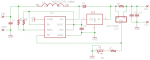
Here is the current board:

The Eagle 6 .brd and .sch are attached.
Ive been pretty busy lately and havent been able to test this out or work on it very much. This is where I need your help. If anybody want to try this thing out (on a testload and scope, not a pl520) that would be great.
Any suggestions on the design would be great too. Ill come back with a digikey parts list and an explanation of how the driver works/some design choices I made, but right now i've got to go")
Ok, here is some explanation.
First for the current setting I used a zxct1009 current amp. It monitors the voltage over a small resistor (R1) on the high side and amplifies it. There are a set of formulas in the datasheet and I have boiled that down into a few simple calculations written down somewhere. I'll geet to those later. Basically you calculate the needed resistance between the output and ground to make the voltage there equal to the regulators FB voltage when the desired current is flowing through your current sense resistor. If you put a pot in series with a resistor between the output and ground you have a maximum current (when calulated with just the fixed resistor) and a minimum (when calulated with the resistor plus the pot's max value) and adjusting the pot will allow you to achieve any value in between. I have used this chip before and it works very well. Also because it senses on the high side it has the wonderful side effect of making a continuous ground.
Second thing I want to talk about is the 3.3v regulator. This is needed because of this drivers ability to run from such low voltages. The control circuitry inside the regulator will not function from ~1v, it needs at least 3v to operate. When the regulator first starts up with a voltage less than 3v it switches the mosfet continuously. This will cause the voltage on the output to rise (builds in the output caps since the green diode has since a high Vf) over 3v and the 3.3v regulator will supply power to the regulators control circuitry from the boosted ~7-8v on the output side. This is called bootstrapping. As soon as there is >3.3v on the output it goes into normal regulated switching mode. Since green and BR diodes have a high vf that whole process will conclude before they even start to conduct, so the startup when using a single 1.5v alkaline will not affect them.
Third, I decided to use two frequency set resistors. In example circuits the frequency set resistor is always on the input side instead of drawing from the bootstraped control circuitry power. I believe the reason is because there must be power on this pin at startup for it to work, otherwise why wouldn't they supply it from the regulated output? The frequency of the regulator varies wildly with both the voltage on the pin and the resistor value. I wanted this to run above 1mhz, which from their charts showed I needed a 75k resistor if the input is 3.3v. Unfortunately if the input is around 1.5v the frequency is very low no matter what resistor you use. I decided I needed to feed this from the regulated 3.3v because the driver absolutely would not work from 1.5v if the frequency was limited so much. But since there is no power at the regulator before startup (which it seems to need) I also put a high value resistor to the input. Now it can run around 200-300khz during startup on 1.5v and switch over to >1mhz once the output reaches 3.3v.
Fourth, I put two pads for output caps. I figure you can use two 22uf ceramics or you could use one ceramic and one high value tantalum. Either way there a quite a bit of capacitance there so it should keep the ripple and spikes away.
Also I haven't found time to organize the silkscreen on the board yet so any you order from those file will look pretty messy and you will have to know where the components go.
Just a quick estimate of the parts,
IC1: lm2623a (vssop8)
IC2: zxct1009 (sot23)
IC3: 3.3v regulator (sot23)
R1: 0.1 ohm (0805)
R2: current setting - calculate later (0603)
R3: current setting - calculate later (pot)
R4: 75k (0603)
R5: >500k (0603) (might not be necessary, have to test and see!)
C1: 22uf ceramic(1206)
C2: 22uf ceramic(1206)
C3: 22uf ceramic or maybe a bigger tantalum (1206)
C4: 1uf ceramic (0603)
D1: Same as benboost mini
L1: Same as benboost mini
And there's my 1000th post :beer:
When the pl520 green diodes came out I had an idea to make a driver for them. I had saw a chip that could run from as little as 0.8v and still boost high enough for a blueray or green diode. How cool would it be to run your laser from either a AA or a 14500? I have a m140 laser with a custom driver set up like this and its awesome.
This driver is based around the LM2623A regulator with a ZXCT1009 current amp.
Here is the lm2623 datasheet:
http://www.ti.com/lit/ds/symlink/lm2623.pdf
Quick specs:
-Run from as little as 1 alkaline (1.5v) battery
-Boost only
-2.85A typical switch current
-Adjustable output
-Max output 14v
Here is the current board:
The Eagle 6 .brd and .sch are attached.
Ive been pretty busy lately and havent been able to test this out or work on it very much. This is where I need your help. If anybody want to try this thing out (on a testload and scope, not a pl520) that would be great.
Any suggestions on the design would be great too. Ill come back with a digikey parts list and an explanation of how the driver works/some design choices I made, but right now i've got to go
Ok, here is some explanation.
First for the current setting I used a zxct1009 current amp. It monitors the voltage over a small resistor (R1) on the high side and amplifies it. There are a set of formulas in the datasheet and I have boiled that down into a few simple calculations written down somewhere. I'll geet to those later. Basically you calculate the needed resistance between the output and ground to make the voltage there equal to the regulators FB voltage when the desired current is flowing through your current sense resistor. If you put a pot in series with a resistor between the output and ground you have a maximum current (when calulated with just the fixed resistor) and a minimum (when calulated with the resistor plus the pot's max value) and adjusting the pot will allow you to achieve any value in between. I have used this chip before and it works very well. Also because it senses on the high side it has the wonderful side effect of making a continuous ground.
Second thing I want to talk about is the 3.3v regulator. This is needed because of this drivers ability to run from such low voltages. The control circuitry inside the regulator will not function from ~1v, it needs at least 3v to operate. When the regulator first starts up with a voltage less than 3v it switches the mosfet continuously. This will cause the voltage on the output to rise (builds in the output caps since the green diode has since a high Vf) over 3v and the 3.3v regulator will supply power to the regulators control circuitry from the boosted ~7-8v on the output side. This is called bootstrapping. As soon as there is >3.3v on the output it goes into normal regulated switching mode. Since green and BR diodes have a high vf that whole process will conclude before they even start to conduct, so the startup when using a single 1.5v alkaline will not affect them.
Third, I decided to use two frequency set resistors. In example circuits the frequency set resistor is always on the input side instead of drawing from the bootstraped control circuitry power. I believe the reason is because there must be power on this pin at startup for it to work, otherwise why wouldn't they supply it from the regulated output? The frequency of the regulator varies wildly with both the voltage on the pin and the resistor value. I wanted this to run above 1mhz, which from their charts showed I needed a 75k resistor if the input is 3.3v. Unfortunately if the input is around 1.5v the frequency is very low no matter what resistor you use. I decided I needed to feed this from the regulated 3.3v because the driver absolutely would not work from 1.5v if the frequency was limited so much. But since there is no power at the regulator before startup (which it seems to need) I also put a high value resistor to the input. Now it can run around 200-300khz during startup on 1.5v and switch over to >1mhz once the output reaches 3.3v.
Fourth, I put two pads for output caps. I figure you can use two 22uf ceramics or you could use one ceramic and one high value tantalum. Either way there a quite a bit of capacitance there so it should keep the ripple and spikes away.
Also I haven't found time to organize the silkscreen on the board yet so any you order from those file will look pretty messy and you will have to know where the components go.
Just a quick estimate of the parts,
IC1: lm2623a (vssop8)
IC2: zxct1009 (sot23)
IC3: 3.3v regulator (sot23)
R1: 0.1 ohm (0805)
R2: current setting - calculate later (0603)
R3: current setting - calculate later (pot)
R4: 75k (0603)
R5: >500k (0603) (might not be necessary, have to test and see!)
C1: 22uf ceramic(1206)
C2: 22uf ceramic(1206)
C3: 22uf ceramic or maybe a bigger tantalum (1206)
C4: 1uf ceramic (0603)
D1: Same as benboost mini
L1: Same as benboost mini
And there's my 1000th post :beer:
Attachments
Last edited: