Welcome to Laser Pointer Forums - discuss green laser pointers, blue laser pointers, and all types of lasers

LPF Donation via Stripe | LPF Donation - Other Methods

Links below open in new window

ArcticMyst Security by Avery

OPEN SOURCE: "CC-Boost" - 2.4 Amp boost driver - RC1

Joined
Jul 4, 2012
Messages
2,834
Points
63
I don't know. Frankly, I hate pots, and never use them, for pretty much this reason. My perspective (and I've held it for a long time) is that people should set the currents they need, and not rely on a crappy 40 cent component to control the current to their diodes. I have never liked the behavior of pots on drivers, with the possible exception of the $5 multi-turn pot I put on the 10A buck driver I sent ARG. That one behaved fairly well, and gave me the range I was expecting.

That said, I'm pretty sure the cheap single turn pots have ginormous +/- tolerances... maybe even as high as 10%?

EDIT: I was wrong about tolerance... lol... I wasn't ginermous enough. Turns out those single turn pots have +/- tolerances of 25% !
3303X-3-501E Bourns Inc. | 3303X-501ECT-ND | DigiKey

So I'm basically no help to you on this point, sorry :( Someone who uses the pot-version may be able to help. But I would suggest just ditching them and setting fixed current properly.

Agreed, these little pots suck. pots like these have always seemed to be quite nice anytime I have used them (not that exact one, but that style). Bit beefier, but of course more expensive- not to mention that trying to put one on a driver this small would be ridiculous :p

For now I will go with "The IC overheated," though it didn't feel at all hot when I was done reflowing it. I will try TLS's method of heating the IC from the underside of the board next, see if it yields different results.

This may be a complete n00b question (oh wait, yea, it is), but what is the formula for the set resistor? Shouldn't there be a reference voltage?
Edit: datasheet says .6V. Theres no reason it should be any different, is there?
 
Last edited:


rhd

0
Joined
Dec 7, 2010
Messages
8,475
Points
0
This may be a complete n00b question (oh wait, yea, it is), but what is the formula for the set resistor? Shouldn't there be a reference voltage?
Edit: datasheet says .6V. Theres no reason it should be any different, is there?

That's a good question actually, and it's not straight forward (well, the answer is, but the reason isn't).

The formula is: 800 / current (amps) = resistance (ohms)
*** when using the sense resistance of 0.075 ***

The reason, is that we screw with the reference voltage by basically tricking the IC using the ZXCT1009. So the IC's reference voltage is irrelevant (except to the extent that it factored into the original derivation of the formula above).

You already got a fixed RSET on the board... I think it's 300 ohms? or 320 ohms?

Probably your best approach is to replace the RSET with a ~350 ohm resistor. Then remove the pot and bridge its pads together. You should get around 2.3A.
 
Last edited:
Joined
Jul 4, 2012
Messages
2,834
Points
63
That's a good question actually, and it's not straight forward (well, the answer is, but the reason isn't).

The formula is: 800 / current (amps) = resistance (ohms)
*** when using the sense resistance of 0.075 ***

The reason, is that we screw with the reference voltage by basically tricking the IC using the ZXCT1009. So the IC's reference voltage is irrelevant (except to the extent that it factored into the original derivation of the formula above).

You already got a fixed RSET on the board... I think it's 300 ohms? or 320 ohms?

Probably your best approach is to replace the RSET with a ~350 ohm resistor. Then remove the pot and bridge its pads together. You should get around 2.3A.

Thanks. I knew it wouldnt be just straight forward :p
I hope you aren't asking me what the RSET on the board is, because I don't have the slightest clue :D
I will try again tomorrow with a new board, if its still wonky then I will try the resistor to set current. If I added a 350 ohm resistor, I would remove the two .15 ohm resistors, correct?
 

rhd

0
Joined
Dec 7, 2010
Messages
8,475
Points
0
Thanks. I knew it wouldnt be just straight forward :p
I hope you aren't asking me what the RSET on the board is, because I don't have the slightest clue :D
I will try again tomorrow with a new board, if its still wonky then I will try the resistor to set current. If I added a 350 ohm resistor, I would remove the two .15 ohm resistors, correct?

Nope. Those are the RSense resistors. Keep them.

There's a resistor that's 300 ohms, roughly. Just glance at the parts you ordered, there's only one. Swap that with roughly 350, and then bridge all the pot pads (well, as long as you bridge the two parallel pads, you're fine)
 
Joined
Aug 14, 2013
Messages
2,655
Points
63
The ones I did were also whining. I think
it's either too much/too long heat during
reflow or something to do with the test
setup. It could also be the pot too, who
knows. The boards I did were the same RC1
with the pot.
 
  • Like
Reactions: ARG

rhd

0
Joined
Dec 7, 2010
Messages
8,475
Points
0
The ones I did were also whining. I think
it's either too much/too long heat during
reflow or something to do with the test
setup. It could also be the pot too, who
knows. The boards I did were the same RC1
with the pot.

Why don't you guys give Beta15 a shot? It's the same driver, minus the pot that I added at the very end due to (unfortunate) popular request ;)

http://www.filedropper.com/beta15

I think it's beta 15 that ARG tested, right before the pot was added. I wouldn't be surprised if the pot has something to do with your issue.
 
Joined
Jul 4, 2012
Messages
2,834
Points
63
Down with the pots! Down with the pots! Down with the pots!

I am surprised at how nice this board looks. No residue, all solder pads are nicely filled, everything is centered. Did not expect anything near this nice on the first [successful] go. I'll see if I can get my camera to focus on it so I can take a pic.

I may make a few of those (v15b) as well, depending on how well this current batch works out. What is the status of that smaller footprint fork, this one? It obviously isn't the same parts, so me building a bunch would be pointless without getting it scoped first. However, I would be willing to make some for someone to scope, if that would help :)
 
Last edited:

ARG

0
Joined
Feb 27, 2011
Messages
6,772
Points
113
What is the status of that smaller footprint fork, this one? It obviously isn't the same parts, so me building a bunch would be pointless without getting it scoped first. However, I would be willing to make some for someone to scope, if that would help :)

It looks like it has a pot and a DFN package. Those are harder to solder than SOIC.
 

rhd

0
Joined
Dec 7, 2010
Messages
8,475
Points
0
What is the status of that smaller footprint fork, this one? It obviously isn't the same parts, so me building a bunch would be pointless without getting it scoped first. However, I would be willing to make some for someone to scope, if that would help :)

To be honest, I made one of the smaller footprint forks, and it output 1.7A, but turning the pot resulted in non-sensical results (it would jump strangely), so I tossed it, and never did anything further with the design.

Maybe the pot was my issue, lol. I didn't put much further thought into it.
 
Joined
Jul 4, 2012
Messages
2,834
Points
63
dang, didnt realize that. Can't be too much more difficult with hot air, right?

and it was on that day, that his famous last words were uttered.
 
Last edited:

ARG

0
Joined
Feb 27, 2011
Messages
6,772
Points
113
dang, didnt realize that. Can't be too much more difficult with hot air, right?

and it was on that day, that his famous last words were uttered.

The problem with the smaller pads is that surface tension doesn't do as much work for you as with the larger pads. Positioning of the paste, and the amount used are now important factors in getting it soldered right. They are a pain to do without a stencil.
 
Last edited:

rhd

0
Joined
Dec 7, 2010
Messages
8,475
Points
0
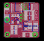
Here, this is the board to test if we want to miniaturize and have a better, higher current boost. It uses the EUP chip, but it's a fixed resistor. It's not smaller itself, but it would prove the design.

http://www.filedropper.com/aanewopenboosthcv03b

attachment.php
 

Attachments

  • board.png
    board.png
    55.3 KB · Views: 125
Last edited:

IWIRE

0
Joined
Dec 18, 2013
Messages
630
Points
0
1) it emitted a very high pitch tone, even though Vload>Vbattery. Tone lowered in frequency as I increased the current (and thus the load voltage)
2) I fiddled around with the number of diodes (don't have a current&voltage chart handy for them) and when I got it to around 5V (thinking 445) it not only would not increase past ~1700mA (using 2x.15ohm set resistors), but got very, VERY hot very quickly. I am pretty sure I actually burned my finger a bit.
edit: as it heated up, the current output started to drop steadily, and I imagine it would have continued to drop if I would have left it powered on.
One of the three drives I built made that noise. I thought it was weird but I had heard the same noise from some other drives before. Mine got pretty warm pretty quick. I embedded the inductor in a blob of thermal adhesive and used a strip of copper from the chip to the host.
Those were built using an iron. I'm hoping this weekend to try the toaster oven. It will be with the same order of components so if something goes bad I'll know I still suck at reflow.
 
Joined
Aug 14, 2013
Messages
2,655
Points
63
To be honest, I made one of the smaller footprint forks, and it output 1.7A, but turning the pot resulted in non-sensical results (it would jump strangely), so I tossed it, and never did anything further with the design.

Maybe the pot was my issue, lol. I didn't put much further thought into it.

I think this may be a limitation of the
type of current monitoring used in the
ZXCT. I was doing a SPICE simulation of it
and changes like that seem to cause the
current measurement to get out of sync.

Here are shared projects on OSH Park for
the new boards. I turned off thermals on
all the pours since having 0 thermal
isolation was confusing the OSH Park script
and causing it to still generate really
tiny glitchy looking thermals. It didn't
look like you wanted them anyway.

CCBoost™ 15b by rhd
CCBoost HC™ v0.3b
 
Last edited:
Joined
Jul 4, 2012
Messages
2,834
Points
63
well, bother. I reflowed another, doing it slightly different as to not overheat the IC- which worked, the IC was barely warm when I was done. However, same story- only output 1.78A@~5.2V, and got extremely hot. Even with the inductor heatsinked, the IC got so hot I burnt myself (again- i should stop doing that, eh?). Not sure what the deal is. Since I have the parts I will probably just make the rest, but then be done with these- maybe I just have bad luck. Or, maybe the IC's are knockoffs- I am not sure where/what seller Rifter (who I bought them from) got them from. I think I will try benboosts next, at least I know 100% certain those work :)
Not trying to imply these don't work, they obviously do- I am just obviously not having any luck with them.


Top