Welcome to Laser Pointer Forums - discuss green laser pointers, blue laser pointers, and all types of lasers

LPF Donation via Stripe | LPF Donation - Other Methods

Links below open in new window

ArcticMyst Security by Avery

Odicforce Boost Driver?

Joined
Feb 4, 2010
Messages
3,280
Points
113
UPDATE WITH RESULTS

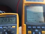
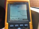
This driver is a constant VOLTAGE (CV) driver, and not constant current (CC). Meaning pot adjustments on the board will alter the voltage the driver supplies, and the amperage will adjust accordingly..... which is not so good for diodes especially as they warm up.

tl;dr -- don't use this driver


Results from jnrpop:

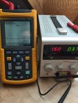
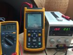
This was the conclusion from my testing:


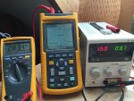
Driver 1: min 145mA max 400mA @ 6.5V out
Driver 2: min 210mA max 410mA @ 6.5V out

Driver 3: min 460mA max 745mA @ 4.5V out

------------------------------------------------------
Driver 1 & 2 was the 0-300mA 515-520nm boost driver from Odicforce
Driver 3 was the 50-1800mA 450nm Boost driver from Odicforce

Someone else will have to confirm if this Driver is indeed CV or CC, i can send High def pics if someone wants them.
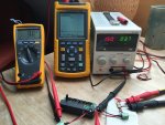
My testing procedures, instruments, testload are all setup to the best of my knowledge and ive used the same setup to test other drivers and set them with no problems. Also i must say the other drivers i have set , x-boost, ebay drivers have all acted the same way; change in I with the + or - of Testload diodes :D


And a word from paul with CV being an issue...
The problem with using constant voltage regulators for laser diode drivers is the Vf is held constant while the current is allowed to increase with temperature and current. A driver should hold the current constant while allowing the Vf to change. It might not destroy the diode immediately, but it will eventually.....especially with longer duty cycles. Don't just take my word for it. Ask anyone you respect for their knowledge on drivers and laser diodes. I won't be using mine as configured. If you do, I hope you don't lose it on the first time out.​

__________________

ORIGINAL POST


So I've been scouring around for drivers for the new 475nm and 505nm diodes... anyone have any experience with these?

Variable Boost Driver Board for 515nm and 520nm Green Laser Diodes - OdicForce

And if they're good, I'm also looking around for 488nm diodes which have very similar power requirements (6-7.5Vin 110ish mA). I would dare feed the 502 the nano's 275mA, but not a super expensive 488.

--

Are these drivers known to be good, bad, or unknown? If unknown, would anyone be able to test them for stability?

Conclusion: find something else
 
Last edited:


Joined
Sep 20, 2013
Messages
17,441
Points
113
I've seen them on eBay lately. They sell for under $10.00 there. I believe the current range on the ones on eBay are 1.3 to 1.5 amps, so it would not work for this diode if it is the same driver.
 
Joined
Sep 20, 2013
Messages
17,441
Points
113
Looks just like the eBay one. Can't say for sure what current output of this one is. It might work out if that is the range.

Edit: I was scanning their other drivers and found some others that could work well for this diode.
 
Last edited:
Joined
Mar 27, 2011
Messages
507
Points
63
We need to make sure that those driver are current regulated instead of voltage regulated.
 

jnrpop

0
Joined
Dec 7, 2008
Messages
723
Points
63
Ordered a couple of these, i'm in the EU so should be here soon and ill do a test.
Be great if these are current regulated drivers, 6-7v @ 50-300mA outputs with no voltage spikes and very small current ripple...Let's hope :beer:
 

Encap

0
Joined
May 14, 2011
Messages
6,126
Points
113
You can always contact by phone or email - Jonathan Slater/Odic Force and ask him which if any of the 20 or so drivers he offers he would suggest based on your requirements. He can answer any questions you have about them as well.

Phone: +44 (0) 777 5785574 Contact person: Jonathan Slater Email: ofl@odicforce.com

see: Contact information - OdicForce
 
Last edited:
Joined
Sep 20, 2013
Messages
17,441
Points
113
I hope to get the one I ordered in the next week. I'll post the results as soon as I do.
 

jnrpop

0
Joined
Dec 7, 2008
Messages
723
Points
63
Thanks for the info :beer:
I sent an email but no reply yet,
I'll try give Jonathan a call next week, My order has been sent so shouldn't take long :D
 
Joined
Sep 20, 2013
Messages
17,441
Points
113
We need to make sure that those driver are current regulated instead of voltage regulated.

They are all claimed to be laser diode drivers. It would be very impractical
for them to be voltage regulators. I will know once mine gets here.
 
Joined
Sep 20, 2013
Messages
17,441
Points
113
Just got notified that my driver is in Stamford, CT. Hopefully, I'll get it soon now.
 

jnrpop

0
Joined
Dec 7, 2008
Messages
723
Points
63
So..good news, I received the drivers today,
Super fast shipping to Germany, 4 days total.
Packaged really well, all drivers came with a Spec sheet and in Static bags.

First thing i notices is that this "515-520nm" boost driver is identical to the 1800mA boost driver they also sell, except one smd Resistor, its a different value.

I can also say the specs for the 515-520nm boost driver from the Spec sheet provided by Odicforce are:
Vin: 3-5V (1x3.7v cell)
Vout: 7.5V
Iout: 50-300mA


I should have time this weekend to do some testing, just got my Fluke scopemeter back so i can test the ripple on startup too :D

Cheers for the fast delivery Odicforce :beer:

attachment.php
 

Attachments

  • lpf.jpg
    lpf.jpg
    106.3 KB · Views: 212
Last edited:
Joined
Sep 20, 2013
Messages
17,441
Points
113
That's great news. I am still waiting for my driver from China, so I won't know anything until it gets here. I hope these turn out to be good drivers as the price is very reasonable.


Edit: I got my driver from China that I paid $8.00 for that is the same driver as the Odicforce ones. I'm hoping to test it very soon.
 
Last edited:
Joined
Mar 27, 2011
Messages
507
Points
63
Just as i thought so, those driver are using IC from Feeling tech, which is good.
Still, it's quite mindblowing that they're able to sell it at about ~$10.

Just seeing from the boards, it looks like they're not directly controlling the current by taking the feedback from sense resistor, but instead giving a constant voltage (5.5V or 7.5V) while current control done by adjusting the overcurrent trip using resistor.
I could be wrong though, but that's what i could say by tracing the PCB trace from the online photos.

This is a good news actually, I never thought this method would work for controlling output current, this will omit the needs of sense resistor and current sense IC.
I always thought that those "overcurrent trip point" set by resistor meant for turning off the IC should the inductor current reach that "trip point". The only downside is that those current trip meant for inductor switch current, not for the output current.
 

jnrpop

0
Joined
Dec 7, 2008
Messages
723
Points
63
Great Paul :D
let's use this thread for the results :beer:

Yr right, the case positive 505 diodes will have to use custom hosts isolating the module if used with this driver, unless the oriantation of the driver components can be changed :thinking:

But for the case neutral 505nm diodes and the 473nm diode it should be fine, also for the 520nm diodes that are available with I<300mA
 

jnrpop

0
Joined
Dec 7, 2008
Messages
723
Points
63
So...preliminary results are up!! and its looking very positive :beer:

Testload set to 10 Diodes = (~7V drop @ 100mA from the scale),
All Fluke meters zero'ed out,
Benchtop P/S set to 1.5A @ 3.7V (1cell)

attachment.php


First run: 280mA, absolutley NO Voltage Spike on startup :beer:

attachment.php

attachment.php


Second run: i set the driver to 150mA using the fluke, NO Voltage spike again

attachment.php

attachment.php


And here the Voltage output from the driver with No Load = ~8V

attachment.php


Anyone want any more info or tests done let me know here :D
 

Attachments

  • 1.jpg
    1.jpg
    139.1 KB · Views: 202
  • 2.jpg
    2.jpg
    121.7 KB · Views: 196
  • 3.jpg
    3.jpg
    107.8 KB · Views: 218
  • 4.jpg
    4.jpg
    100.6 KB · Views: 190
  • 5.jpg
    5.jpg
    118.9 KB · Views: 226
  • 6.jpg
    6.jpg
    102.3 KB · Views: 220
Last edited:


Top