

Hi.
Perhaps this will interest all noobs like me that like to read ? If not it can be deletet.
I know the basics about elektronics but have not been doing mutch since 1979 so many things are new to mee.
I really like all the hints and information that can be found in this forum, and after reading a little about buck/boost I was wondering if I could be making one by myself, so I started google
Around and found some interesting tips on a Swedish forum, and they mentioned TPS63020, I remembered reading about it in something written by “foulmist”.
There was a link to Texas Instruments, so I could read some specifications
DC/DC Converter (Integrated Switch) - Buck-Boost Regulator - TPS63020 - TI.com
3A sounds good enough for me
Further down on the page there was something with input boxes and it sad
“Design Now with SwitcherPro”
I tried to fill in some numbers but I had to be a registered user.
Naturally I registered myself and after some more clicking with my mouse I found TPC63020 again.
Now I could choose to create a new design with this circuit so I did.
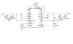
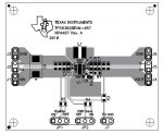
I filled in Vin (min/max), Vout, Iout, Vripple and the tool gave me things like
Schematic, Layout, Component list and so on
( Please see the attachments below )
I could also order the components if I understood everything right.
I hope this info is useful for someone out there.
I guess that the board design easily could be changed to dubbelsided and perhaps even two boards above each other if it will make it smaller.
Now a question from a noob!
I read something about that the normal low voltage protection on TPS63020
might damage the batteries, can this not be fixed by putting a diode in
series with batteri and the circuit? And fool the protection so the batteri has 1 voltage more left ?
Perhaps this will interest all noobs like me that like to read ? If not it can be deletet.
I know the basics about elektronics but have not been doing mutch since 1979 so many things are new to mee.
I really like all the hints and information that can be found in this forum, and after reading a little about buck/boost I was wondering if I could be making one by myself, so I started google
Around and found some interesting tips on a Swedish forum, and they mentioned TPS63020, I remembered reading about it in something written by “foulmist”.
There was a link to Texas Instruments, so I could read some specifications
DC/DC Converter (Integrated Switch) - Buck-Boost Regulator - TPS63020 - TI.com
3A sounds good enough for me
Further down on the page there was something with input boxes and it sad
“Design Now with SwitcherPro”
I tried to fill in some numbers but I had to be a registered user.
Naturally I registered myself and after some more clicking with my mouse I found TPC63020 again.
Now I could choose to create a new design with this circuit so I did.
I filled in Vin (min/max), Vout, Iout, Vripple and the tool gave me things like
Schematic, Layout, Component list and so on
( Please see the attachments below )
I could also order the components if I understood everything right.
I hope this info is useful for someone out there.
I guess that the board design easily could be changed to dubbelsided and perhaps even two boards above each other if it will make it smaller.
Now a question from a noob!
I read something about that the normal low voltage protection on TPS63020
might damage the batteries, can this not be fixed by putting a diode in
series with batteri and the circuit? And fool the protection so the batteri has 1 voltage more left ?


")
