Welcome to Laser Pointer Forums - discuss green laser pointers, blue laser pointers, and all types of lasers

LPF Donation via Stripe | LPF Donation - Other Methods

Links below open in new window

ArcticMyst Security by Avery

NJG-18, multimode boost driver for 445nm.. and possibly 650nm

Joined
Dec 23, 2010
Messages
561
Points
0
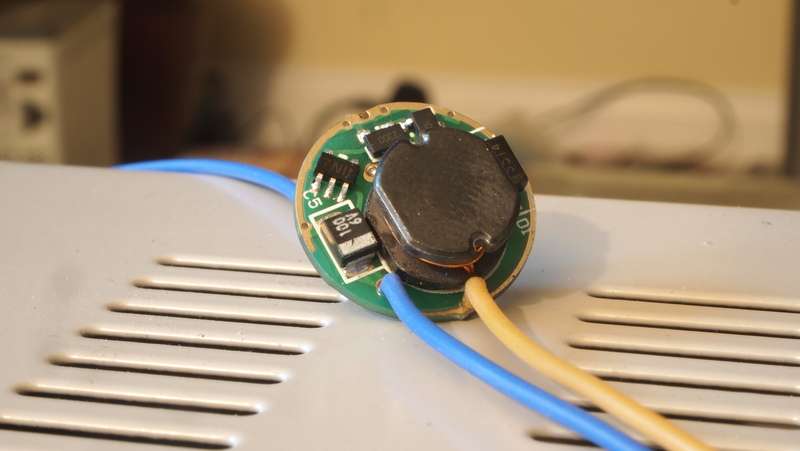
ok i have had very very good results with this driver. i have only blew 1 so far and that was my fault. This driver is a constant voltage driver...so i dont know if a regular testload would work so i never used a conventional testload for it. I use a scrapped XP-G LED with a couple of 1n5401 diodes in series with the positive lead as a test load. Worked for me everytime.

anyways only on 1 build did I keep the modes, otherwise i always bypassed the modes by soldering LD- pin to the outside ring.

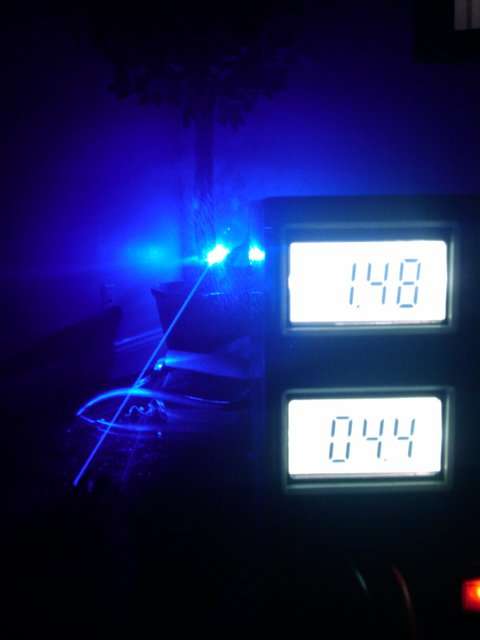
umm if you look at a brand new njg-18, you notice the part that you can turn has a flat side to it. It is normally facing the two resistors, well, for about 1.4A current the pot will be facing 1/3 turn countrer clockwise from that position. sometimes with certain njg-18's i have to turn the pot a full 180 degrees counter clockwise before I can reach 1.45A current.

The only thing with this board that i noticed is that it is really sensitive to damage from a soldering iron. if you keep the soldering iron on any part for more than 10 seconds...the driver will most likely not work anymore. thats the only time I have broken one of these.
 
Last edited:


DTR

0
Joined
Jun 24, 2010
Messages
5,684
Points
113
Sure can. Use this alternative point on the outer edge for the diode negative and either run the battery negative to the other point on the underside opposite to this one or bridge the case pin and the negative pin on the diode. I also really suggest anyone trying to set these drivers that you use a bench supply as your power source. The most common thing I have seen is when soldering into the normal negative hole sometimes you can short the driver. If you are using a bench supply you will automatically know something is wrong because like on mine it will start pulling 5A.:eek: If it does this you can just unsolder it and try again will normally fix it. I am assuming this is what is happening with all the reports of exploding drivers on this thread.:beer:

Also if you test it with batteries and you set it to a specific current but your battery has dropped to say 3.9V and you then hook a diode up to it and pump 4.2V from a fresh battery the current will be way higher than what you had intended.

p1015676.jpg
 
Last edited:
Joined
Feb 5, 2008
Messages
6,252
Points
83
Uhh what? That's can't be possible...

If the power drops with the battery level, that's not a regulator circuit at all? Are you certain of this? Because it sounds incredibly illogical.

Right I'll go ahear and bypass all the modes, see what current settings am I getting.
 

DTR

0
Joined
Jun 24, 2010
Messages
5,684
Points
113
Here is a video that will show what I am talking about with the current.;)

 
Joined
Feb 5, 2008
Messages
6,252
Points
83
Right, appreciate all the help here DTR, but this driver is uhh, well it's first and last time I'm using that one, that's for damn sure.

I have bridged the points and now my readouts are weird in a new way.
Setting for example 800mA (at least I think it's 800mA), measuring takes around 2-3 seconds to slowly climb up to 800 then falls rock bottom 000 ,

Making it 400mA goes up to 400mA, then stays there for second or two, then again starts to drop.

Fiddling with the trimmer a little and now it won't even go above 60mA anymore, as if it's worn out, or degraded like severely overdriven LD.

I hate trimmers and I hate modes.

I have a lot of boards which have bucking drivers from 501B lamps, they are regulated via some sort of LM3410 derivate and use same 190mV referrence as my LM3410X drivers I am working with.

All done 17mm boards, will just set current to 1 A by adding another resistor in parallel and use it as 2x 16340 laser.

Thanks anyway, guys. You da best :)
 
Joined
Dec 23, 2010
Messages
561
Points
0
hmmm i cant say that I have ever had that problem with these drivers. bypassing the modes altogether has seem to work well for me. DTR's photos are always the best. Helps with everything. Like he said as well, using a bench power supply is the best way to set current. it helps in monitoring voltage and current going into the driver and the DMM takes care of reading output. I just need a higher power bench supply now...3A is not enough nowadays.

Hey DTR where'd you get yours at and how much? theres one at electonics store in my city that hits 30V and 5 amps but is like $189...
 

DTR

0
Joined
Jun 24, 2010
Messages
5,684
Points
113
I use a Mastech HY1505D and it is cheap but it has served me very well. I think I payed like $90. I actually had the 3A version then upgraded to the 5A. My only grip is that since I upgraded to the 5A this version does not have a backlight for the LCD which I have no problem seeing but I got much better pictures and videos with my old one. I quite often drive diodes directly with this supply and never had a problem as well.:beer:

I have only needed more with the Phlatlight LED's that I have been playing with.:eg:

Here is a quick ebay search on the model. It has been a while and I am not sure who I got mine from.

hy1505d | eBay


Here is a picture of the old one with the backlight. The camera can really pickup the contrast much better with the light.

20100904001020.jpg


Last edited:
Joined
Dec 23, 2010
Messages
561
Points
0
I got a 3 amp velleman that is very similiar to your 3A mastech. yea, i was curious one time and hooked up a phr and a LOC to mine just to see how stable it was...lit them up fine... cool to know... i noticed alot of 3A bench supplies being sold and they all have backlights while the 5amp, 30V one at Fry's doesnt have a backlight either...weird

dang you paid only $90 for a 5amp. mine was about $80 after tax since i bought it locally at a store. i must upgrade!!!
also, your old one has a much better backlight...the Velleman has the usual ugly green light...its good enough but the contrast is horrible to pick up on camera.
 
Last edited:
Joined
Mar 26, 2010
Messages
3,220
Points
0
So these drivers apparently aren't even CV then.. there's no 'constant' about them. Looks like all your adjusting with the pot is a voltage ratio between input and output, meaning as input drops, output will too. This is different from my original understanding of how these drivers worked. My initial tests made it look like they did maintain a fixed output voltage with varying input voltage, but after messing with a few today, and trying to make a build using one, the observed behavior matches what DTR describes.

Hmm. Maybe I should try to design a constant current driver with modes microflex size. heh.
 
Joined
Dec 23, 2010
Messages
561
Points
0
Hmm. Maybe I should try to design a constant current driver with modes microflex size. heh.

plz do!!! you know we would love you for it!!

although i know jib is very close to making a 17mm round boost circuit board that is capable of over 3 amps.

a square or rectangular shaped board would be a good compliment to this.
 
Joined
Mar 26, 2010
Messages
3,220
Points
0
Well dc-dc circuits aren't complicated.. The miniaturization of one to say, fit inside an aixiz module.. would be the challenge.
 
Joined
Dec 17, 2010
Messages
1,144
Points
48
I have a intriguing question about a build I am doing with a njg-18 driver. I am building a 445nm for someone else; it will be ~1w, running in an 18650, and they want the modes intact. They also want a status led on the host. The way that the host is situated, I hardly have any room for the module and driver; it is a tight fit.

The only place that I have for the led is in the head. So, I drilled a hole in the side, and the led will be mounted there. Anyway, the led needs to be powered on with the laser. I couldn't get to the battery/spring side of the driver without machine work, so I tried something different.

I paralleled the diode and the led together on the output of the njg. The led has a 100ohm resistor on the positive leg. I tried it, and it works. The test load shows a drop of current with the extra led (diode= v drop). Whats really cool, is that the led is bright, dimmer, really dim, strobes, and sos's with the laser on the modes.

My question is; is this bad? Will this setup reduce life of either led or laser diode? Is the extra voltage drop a problem?

Thanks in advance!
 
Joined
Jan 14, 2011
Messages
3,816
Points
63
Hmm... how did I miss that? Anyway, it looks like it has a rather large footprint.


Top