Welcome to Laser Pointer Forums - discuss green laser pointers, blue laser pointers, and all types of lasers

LPF Donation via Stripe | LPF Donation - Other Methods

Links below open in new window

ArcticMyst Security by Avery

New Ultra-Low Drop-Out Constant Current Driver Design!

Joined
Jan 14, 2011
Messages
3,816
Points
63
I found this great IC.

I am able to drive an LOC to 1.25-1.3A from it via a single Li-ion (14500) (of course, on a test load, not an ACTUAL LOC). I did the same test with a different set-up and got roughly half of that.

It's a great configuration, really, it is. The IC itself is capable of handling up to 3A, and it's an ULDO regulator.

I have been struggling with this IC for some time now, trying to use the current source mode on it, but it doesn't seem to want to work. However, I now have a working, stable driver using the "LDO LED driver" sample set-up from the Typical Applications part in the Datasheet.

Anyway, here is the circuit in simple terms:

LT3083driver.jpg


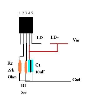
The pins are as follows:
1 - NC
2 - Set
3 - Out
4 - Vcontrol
5 - In

So I actually have no idea how this works, to be honest. But, it works. I have yet to figure out the drop-out voltage yet either, but supposedly, it's only 310mV... it's either that, or 1.25V, anyway. But if it's 1.25V, how am I managing to power an LOC off of it with only a single 14500 at such high load currents?

Anyway, the basic equation for getting the current for your diode is easy:

A = 1.25V/Rset

Not exactly sure what the 27k Ohm resistor does, but it has to be there.

Anyway, what do ya'll think? I think it could be very effective because it's easy to use and there is a possibility of an extraordinarily low drop-out.... Could this be the new DDL drive?

EDIT: I believe the LDO is confirmed. I am capable of running the 4 1N4001 diodes with 3.98Vin from my battery.

Oh, and I know this works for higher voltage situations, too, because I tried it with 6 1N4001 diodes as well, but with a higher Vin.

EDIT 2: While it did start to drop to ~500mA from one 14500 battery with this circuit (when it should have been set at 1.25A), I believe that is due to the resistors dropout from the testload, because I tested the output and it is giving off a steady 3V or so with just one 14500 li-ion. Neat!
 
Last edited:


Joined
Jan 14, 2011
Messages
3,816
Points
63
So the testload isn't very reliable... what I am going to do tonight is try to run it at a small 200mA or so to see if the reason why it keeps on failing is because the testload keeps on overheating (is *is* getting hot at such high currents as 1.2A).

EDIT: Further, I think I may have damaged a 445 when trying to run it at 1.2A with this... but maybe not - will test it with a different driver later tonight.
 

Benm

0
Joined
Aug 16, 2007
Messages
7,896
Points
113
Its not quite the way you are supposed to wire it for a current source. Have a look at the datasheet: LT3083 datasheet pdf datenblatt - Linear Technology - Adjustable 3A Single Resistor Low Dropout Regulator ::: ALLDATASHEET ::: on page 19. These is a clear example of a proper current source, and a low drop led driver. The latter works by adjusting output voltage over a small resistor, with the leds in the input line. I doub't that led source would perform very stably and might produce some current peaks when switching it on...
 
Joined
Jan 14, 2011
Messages
3,816
Points
63
Hmm. Because I wasn't able to get that current source to work. Maybe if we added a cap between the LD+ and the Vin, that would stabilize it? Because that way, we can use the LDO effect of this driver, otherwise it is essentially just an LM1085 or whatever.

And if that is the case, that I may get a current spike when first turning it on... I think I may have already ruined that 445 then. Oh well!

All the same though - would an input cap work to absorb that initial spike?
 
Last edited:

HIMNL9

0
Joined
May 26, 2009
Messages
5,318
Points
0
You need to use a different configuration for these ones ..... i'm testing both the 5-pins DD-PAK and the 16 pind TSSOP case ..... they work, but you need to respect some conditions.

First, you must provide a minimum current through the regulator (like 1mA or few more is enough, but it MUST not be used as open-circuit regulator ..... 1 Kohm resistor directly connected from out and GND is enough) ..... second, provide some heatsinking (especially for the TSSOP package) ..... third, the RSENSE can be lowered to 0.15 ohm, but lower values makes it lightly unstable, anyway with 0.15 ohm, you can use a miniature 10Kohm trimmer for the regulation without too much problems ..... 4th, use 10uF capacitors both at the input and output, for prevent self-oscillation problems.

Also, your circuit is wrong, and the unit is VLDO (300mV dropout) only if you provide a Vcontrol higher than Vin, otherwise is a simple LDO (still 1.2V dropout) ..... for our use, Vcontrol and Vin must be connected together ..... the RSENSE go in serie from the OUT pin to the load, and the trimmer must be connected from the positive of the load (after the RSENSE) and the SET pin.

Also, remember that the maximum input voltage is different from the TO and DD package, and the TSSOP package ..... the "power" ones can hold 15V, 18V max, but the small ones can hold only 7V, 8V max)
 
Last edited:
Joined
Jan 14, 2011
Messages
3,816
Points
63
I don't understand. In my circuit, the Vin *is* lower than the Vcontrol (because of the voltage drop of the diode).

The reason I am not using this as a direct current source is because I *wanted* it to be the VLDO regulator, and not just a normal LDO. That's why this is not your normal set-up. With this set-up, the drop-out *is* around 300mV.

Let me say that again - this is not your normal constant current source with a similar architecture of the DDL drive, where the Vcontrol needs to be connected to the Vin. This one is a completely different design schematic, used with a constant current drive. I am going to continue to work on this circuit in order to make the current extraordinarily stable at start-up so that I can keep it in this mode instead of in constant current mode... because this is *essentially* constant current, just with a current spike at start-up.
 

HIMNL9

0
Joined
May 26, 2009
Messages
5,318
Points
0
Oh, so you are trying to use it, basically, as a current sink, instead source, using the Vin as sink input for the current regulation ..... yes, it can work, but it have more resistors values limits, in this configuration ..... i tried to lower the sink resistor from out to gnd til 0.25ohm (4 x 1ohm in parallel) and trying to use a 5Kohm trimmer ..... it was regulating til 1A, but i was using a bank of "star" emitters as load, and they change a bit when they heat ..... also, it was becoming a bit "floating" reaching 1A, so i stopped to try with that configuration ..... maybe i have to take out the old PCB and do some other experiment, when i find a bit of time.

About the "spike" at the start, i partially solved it connecting a small (470pF) capacitor in parallel with the trimmer, and a fast diode (1N4148) between the SET and the Vcontrol, with the cathode at Vcontrol (in reverse, basically), but not solved completely ..... anyway, worth the try playing with the capacitor value (but must be kept low value, otherwise the current regulation feedback delay too much, and the unit can become unstable.
 
Joined
Jan 14, 2011
Messages
3,816
Points
63
Think that this could work? And why would increasing the cap value be damaging? I can imagine it would just reduce spike even more... and I don't mind if there is a 1 secnod delay on start-up... it would be kind of nice, actually.

And by the way, I didn't understand this sentence: " yes, it can work, but it have more resistors values limits, in this configuration "

Can you repeat that?
 
Last edited:

HIMNL9

0
Joined
May 26, 2009
Messages
5,318
Points
0
Uhm, no, wait.

Increasing the cap value will not damage anything in the circuit, but can slow down the response time of the IC when it need to regulate the current ..... this is not a problem when it become a slow turn-on, but may become a problem in the opposite sense, when for some reason the current increase, and the IC need to lower it quickly ..... if it need more time for lower the current, the load get the higher current for more time ,and can burn (LDs are more sensitive than LEDs to overcurrents, especially if they are already in use and hot).

So, i suppose a "slow" turn-on of, say, 100 milliseconds can be enough for reduce the current spike, and acceptable as delay time in current regulation, but a second is probably too much ..... and cause the internal reference is a 50uA current only (this IC works directly in current, not in voltage reference), also a small capacitor can increase the time too much.

About the "resistor value limits" thing, sorry, English is not my main language ..... i only mean that, when you use it as current source, the RSENSE value is less critic, and can be played with more (wider ?) range of values (like, using only 0.1 ohm as RSENSE, instead of the rated 0.33 ohm one, gives a more "critic" regulation, but still work decently), where instead using it as sink, connecting the load between positive and input and having a resistor between the out and GND for get a current reference, it work only inside a certain range of values, and don't work well, or become unstable, using too low or too high resistors (this thing about lowering the sense resistors is due to the fact that, more the resistor is high, more you have a dropout on it and power that need to be dissipated, at high currents ..... as example, an 1 ohm resistor at 1A, still add an extra 1V dropout and need to dissipate 1W, where if it was possible to use 0.1 ohm, it only add 0.1V dropout and need to dissipate only 100mW at 1A.

If i find where i've throwed that damn PCB, i may do some other tests, but i need to find it, before :p
 
Joined
Apr 7, 2011
Messages
37
Points
0
Wait... So you hook up the positive lead of the LD directly to the input voltage? Anyway, that is very efficient, cool driver
 
Joined
Jan 14, 2011
Messages
3,816
Points
63
Yup. The driver works as a current sink instead of as a current source.
 
Joined
Jan 14, 2011
Messages
3,816
Points
63
Looking at this thread again, I will begin work with this IC again some time soon. I just have trouble working with these D2PAK packages because of the lack of PCBs. But, once I get some PCB drill bits, I will start testing out lots of different drivers because I now have the ability to create PCBs at home.
 
Joined
Apr 23, 2011
Messages
212
Points
0
Is there any real threat of input spikes? Aslong as its temporary it shouldn't damage anything correct? It basically the same principle as PWMing. You can put in alot more than the rated current aslong as you use a low duty cycle with proper heatsinking?

Its an expensive test but i'm betting if your duty cycle is very low you could probably run 3A through a 445nm 1W diode no problem? Diode will only fry if it gets to hot. Am I correct? Or can the diode heat up enough from that fast spike to destroy it? I'm guessing not. In a commercial product you might want it but for realist home use, caps shouldn't be necessary.
 
Last edited:
Joined
Jan 14, 2011
Messages
3,816
Points
63
Unfortunately, diodes can fry from something called COD (catastrophic optical damage) which can occur nearly instantaneously from a huge overcurrent.
 

rhd

0
Joined
Dec 7, 2010
Messages
8,475
Points
0
I am STILL stumped by how you could drive a LOC at full current, when this config is still dropping 1.25V minimum, because of the RSET ?

Effectively, the highest voltage your LOC has available to it, will be 3V. That's not enough to max out the current of the LOC.

If you're using a test load, make sure you're using 4 diodes, not the normal 3 that we'd often use for LOCs. At the point where a LOC hits its max current (say, 600mA or so), the Voltage requirement is somewhere between 3.4 and 3.8V (depending on which charts you trust). That really needs at least 4 diodes in a test load in order to properly test. Depending on the Vdrop of the diodes, and the Vf you decide to trust for the LOC figures, maybe even 5.
 
Last edited:
Joined
Jan 14, 2011
Messages
3,816
Points
63
So I totally lied about that. When I mean max current of an LOC, I mean 420mA. Effectively the "safe" max current. :p

Even then, I am not sure that I got even that....

Huh. That's weird... I managed to get 1.2A from it?

Disregard what I had to say... I was probably wrong.
 
Last edited:


Top