benmwv
0
- Joined
- Sep 10, 2010
- Messages
- 1,380
- Points
- 48
The problem with that is your meter has be hooked up to it constantly. Usually I take my meter out and measure the total voltage drop while it is running, so you would need to use two meters.


You're both missing the point entirely, I'm afraid. It's not about whether it will melt (that calculation is easy to make), it's about how accurate the reading is.
The resistance of a resistor increases at it heats up. If you send a lot of power to it, it heats up and the resistance slowly increases. With a constant current through it, the voltage drop across the resistor will increase as it heats up. The current appears to climb. This is a false reading.
I can only afford one fluke, and I don't trust my other meters much
I can only afford one fluke, and I don't trust my other meters much, especially when it is so easy to move a probe and measure it with the fluke.
Where does the heatsink go on the component side
or the solder side ??
I also think the Heatsink radiating surface area seems
a bit low...:undecided:
Jerry
You can contact us at any time on our Website: J.BAUER Electronics
") Have you been able to test if there is any resistance in the jumper connections at high currents? I wouldn't think there would be much, posts are big, and the piece of metal that connects them inside that jumper piece has fairly high cross section.
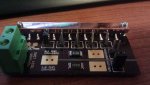
Have you been able to test if there is any resistance in the jumper connections at high currents? I wouldn't think there would be much, posts are big, and the piece of metal that connects them inside that jumper piece has fairly high cross section.The entire back side of the PCB is a copper layer, with vias holes that go to the resistors.I think for this test load's purpose, they just want high thermal mass with good thermal conductivity, not so much for shedding heat into the air at any high rate.
Also, while mounting to the back of the board where the vias come through, maybe would like to employ some thermal tape or other method of redundant insulation besides soldermask if you wanted to.
Is the rest of the back layer of the board heatsinking for the resistors?
A very nice looking piece, there
Make me wonder that DTR has tons of the M140 projector heatsink of the diode array.
If somehow the aluminum sink could match this testload then we shouldn't be worried about the overheating the diodes.