Welcome to Laser Pointer Forums - discuss green laser pointers, blue laser pointers, and all types of lasers

LPF Donation via Stripe | LPF Donation - Other Methods

Links below open in new window

ArcticMyst Security by Avery

New boost driver with IMS PCB

Joined
Mar 18, 2012
Messages
173
Points
0
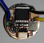
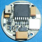
Here is my new high power and thermally efficient boost driver:
- insulated aluminum substrate (IMS) PCB for exceptional thermal efficiency
- current output exceed 2.5A
- very high precision current control and multi-tourn trimmer
- grounded load (only 1 wire to connect)
- open and short load protection
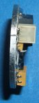
The PCB can be connected directly to the heatsink to obtain a perfect thermal contact.
The board is currently under tests and performs very well. :yh:
It is possible to make commercial boards if anyone interested.

37113d1332052710-new-boost-driver-ims-pcb-photo1.jpg


37114d1332052710-new-boost-driver-ims-pcb-photo2.jpg


37115d1332052710-new-boost-driver-ims-pcb-ims.jpg
 

Attachments

  • photo1.jpg
    photo1.jpg
    157.9 KB · Views: 1,944
  • photo2.jpg
    photo2.jpg
    60.2 KB · Views: 1,445
  • ims.jpg
    ims.jpg
    71 KB · Views: 3,135
Last edited:


Joined
Mar 18, 2012
Messages
173
Points
0
Looks nice price?? And it looks quite complicated

The IMS PCB costs the same as a dual layer standard FR4 PCB. The technology limit is that an IMS PCB is a single layer PCB.
The circuit has an advanced current control to maintain an high efficiency.
As an example a driver based on TPS63020 with standard schematic uses a shunt resistor of value 0.5/Iload. For 2A output the resistor is 0.25ohm so the thermal power dissipated only by the shunt resistor is R*I^2=1W !!! reducing significantly the total efficiency of the driver and battery life.
The advanced current control reduces the dissipation of a factor of 25 and increases the control precision. The additional circuitry is almost ininfluent on total cost.
 
Last edited:
Joined
Dec 11, 2011
Messages
4,364
Points
83
My only question is how the designer compensated for the stray capacitance of the PCB, and how, if at all, it affects the circuit. It looks wonderfuly designed though, that is for sure.
 
Joined
Mar 18, 2012
Messages
173
Points
0
my only question is how the designer compensated for the stray capacitance of the pcb, and how, if at all, it affects the circuit. It looks wonderfuly designed though, that is for sure.

I have observed no differences in circuit behaviour between standard FR4 PCB prototype (attached photo) and IMS PCB. The stray capacitance has negligible effects.
Many thanks for the compliments :yh:

attachment.php
 

Attachments

  • driver_prototype.jpg
    driver_prototype.jpg
    74.7 KB · Views: 1,676
Joined
Mar 18, 2012
Messages
173
Points
0
Sounds pretty great, since we need 1.8A at most..

I'm building a 445nm laser with this driver and an Ultrafire C8 host. I'll post pictures very soon

attachment.php
 

Attachments

  • Ultrafire_C8.jpg
    Ultrafire_C8.jpg
    33.5 KB · Views: 2,970
Joined
Sep 20, 2008
Messages
17,622
Points
113
Nice job on the design...:gj:
What is the diameter of that PCB ??


Jerry
 
Joined
Mar 18, 2012
Messages
173
Points
0
Last edited:
Joined
Mar 29, 2011
Messages
1,056
Points
48
nice build! somewhat big but still nice :p

What's the input/output voltage range?
 
Last edited:
Joined
Mar 16, 2011
Messages
470
Points
0
I would like to try a boost driver one day, for a handheld, I can make one for a labby, but for handheld I have used nothing but linear so far because of availability as I have been doing this a little less than a year, so I am going to lurk this thread to see what happens, but you have my interest.:beer:
 
Joined
Mar 18, 2012
Messages
173
Points
0
nice build! somewhat big but still nice :p

What's the input/output voltage range?

The input voltage range is 2.4V to 25V.
The output voltage absolute limit is the maximum switch voltage of 42V. The current control circuit limits the output voltage to 12V to protect output capacitors but this value can be easily changed replacing a component and using higher voltage output capacitors. The maximum switch current is 6A.
The driver can supply more than one laser diode connected in series.
 
Joined
Dec 29, 2009
Messages
3,136
Points
63
You know, folks in the flashlight arena need a nice, high-current boost driver too. The current generation of emitters is generally powered up at about 3A, dropping ~3.3V across each LED, and wired in series. It would be bomb to have a sleeper light that blasts out ~3000lm off of one 18650 sized cell ;-) What sort of input voltage and current requirements would need to be met to get this to push 3A at 10.5V?
 
Joined
Mar 18, 2012
Messages
173
Points
0
You know, folks in the flashlight arena need a nice, high-current boost driver too. The current generation of emitters is generally powered up at about 3A, dropping ~3.3V across each LED, and wired in series. It would be bomb to have a sleeper light that blasts out ~3000lm off of one 18650 sized cell ;-) What sort of input voltage and current requirements would need to be met to get this to push 3A at 10.5V?

The "magic word" is efficiency. It's not trivial to exact calculate the efficiency of a boost converter.
Here you can find an article with problem analysis.
Anyway let's try to do a simple estimation. The power required for your "thermonuclear torch :)" is 3*10.5=31.5W
Suppose to have a converter efficiency of 80%... The input power required will be 31.5/0.8=39.375W... with a single 3.7V cell the required current is 39.375/3.7=10.642A !!! too much for the cell and for the driver.
If you try to recalculate with 2 cells (7.4V) and the same efficiency the current will be 5.32A. This value is very close to the switch limit of 6A and probably beyond the cell's possibilities...
If you try to recalculate with 3 cells (11.1V) the voltage is greater than that required by your leds (10.5V) so you can use a buck (better efficiency) or linear regulator (worst efficiency)...
...or you can use two boost drivers each with half load... the limit is fantasy:yh:
 
Joined
Dec 29, 2009
Messages
3,136
Points
63
Oh, I see, this is why you mentioned the 6A switch current limit earlier! Thanks for that explanation :wave:
 

DTR

0
Joined
Jun 24, 2010
Messages
5,684
Points
113
Wow that look awesome. Great work.:beer:

Would you have the ability and desire to post a test video for us like the one below. The main thing I would like to see is if the current stays constant @ 1.8A as the voltage decreases. Here is one I tested that did not.:yh:


Top