Long story short, I have a 20mW red 658nm diode that I'm trying to use with a small driver. And I don't know where to solder what!
There are several solder surfaces, and the voltages and polarities between them vary (upon connecting a battery to the two that logically must be for DC in... I think). Power comes from a normal CR2023 3V button battery. The diode is rated for 3V and <38mA, while the driver can handle 3V and 20-40mA.
There is a potentiometer, but turning it seems to do jack squat except at a very precise angle where voltage between certain surfaces drops considerably. It can be turned around and around and around to no end, so there's no way of knowing where "zero" and "max" is.
The driver seller is Chinese, and while he does know some English the language barrier is considerable. There were no specs as to what surfaces on the driver are for what, and he isn't very good at explaining. From the item description;
After a few emails I managed to get him to produce this for me;

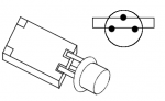
Please see these pictures where I've labeled the surfaces. I would have shown them here using tags, but they're a bit big for that. Do feel free to ridicule my soldering! ;3 [I](note to self: buy new soldering iron)[/I]
[list][*][url=http://i.imgur.com/463Kv.jpg]Front (empty)[/url]
[*][url=http://i.imgur.com/1seaa.jpg]Back (empty)[/url]
[*][url=http://i.imgur.com/rahM7.jpg]Front (with cabling)[/url]
[*][url=http://i.imgur.com/lrbST.jpg]Back (with cabling)[/url][/list]
I [i]*assume*[/i] that surfaces [b](a)[/b] and [b](b)[/b] are the same as surfaces [b](e)[/b] [b](f)[/b]. Stop me if I'm wrong.
[list][*]The 3V battery is connected at [b](a)+[/b], [b](b)-[/b].
[*]Between [b](g)[/b] and [b](c)[/b], there is a potential of about +2.7V. If I reverse the polarity of the batteries, this potential reads at <0.3V, so I think I have the batteries right.
[*]Between [b](c)[/b] and [b](d)[/b], there is a potential of about -2V (iirc).
[*]Between [b](g)[/b] and [b](d)[/b], there is a potential of about +0.6V (iirc).
[*]There is negligible resistance (~0.3 Ohm) between [b](c)[/b] and the pot.
[*]Turning the pot, the resistance between it and [b](d)[/b] varies, from which follows that the resistance between [b](c)[/b] and [b](d)[/b] varies.[/list]
What am I missing? Where is the "triangle" to which I can solder "to the natural order"? [b](c)[/b] + [b](d)[/b] + pot? To begin with why doesn't the pot seem to be doing much at all? Broken? (I bought an extra driver so if necessary I can bin this one.)
Thanks in advance for any help whatsoever, I'm really stuck here.
There are several solder surfaces, and the voltages and polarities between them vary (upon connecting a battery to the two that logically must be for DC in... I think). Power comes from a normal CR2023 3V button battery. The diode is rated for 3V and <38mA, while the driver can handle 3V and 20-40mA.
There is a potentiometer, but turning it seems to do jack squat except at a very precise angle where voltage between certain surfaces drops considerably. It can be turned around and around and around to no end, so there's no way of knowing where "zero" and "max" is.
The driver seller is Chinese, and while he does know some English the language barrier is considerable. There were no specs as to what surfaces on the driver are for what, and he isn't very good at explaining. From the item description;
Pin definition: designed pad especially for 650nm with a PD function of the driver board, you just need to solder pins on the triangle to the natural order, not the same as the other board, to cut off one foot, or staggered welding!
After a few emails I managed to get him to produce this for me;
Please see these pictures where I've labeled the surfaces. I would have shown them here using tags, but they're a bit big for that. Do feel free to ridicule my soldering! ;3 [I](note to self: buy new soldering iron)[/I]
[list][*][url=http://i.imgur.com/463Kv.jpg]Front (empty)[/url]
[*][url=http://i.imgur.com/1seaa.jpg]Back (empty)[/url]
[*][url=http://i.imgur.com/rahM7.jpg]Front (with cabling)[/url]
[*][url=http://i.imgur.com/lrbST.jpg]Back (with cabling)[/url][/list]
I [i]*assume*[/i] that surfaces [b](a)[/b] and [b](b)[/b] are the same as surfaces [b](e)[/b] [b](f)[/b]. Stop me if I'm wrong.
[list][*]The 3V battery is connected at [b](a)+[/b], [b](b)-[/b].
[*]Between [b](g)[/b] and [b](c)[/b], there is a potential of about +2.7V. If I reverse the polarity of the batteries, this potential reads at <0.3V, so I think I have the batteries right.
[*]Between [b](c)[/b] and [b](d)[/b], there is a potential of about -2V (iirc).
[*]Between [b](g)[/b] and [b](d)[/b], there is a potential of about +0.6V (iirc).
[*]There is negligible resistance (~0.3 Ohm) between [b](c)[/b] and the pot.
[*]Turning the pot, the resistance between it and [b](d)[/b] varies, from which follows that the resistance between [b](c)[/b] and [b](d)[/b] varies.[/list]
What am I missing? Where is the "triangle" to which I can solder "to the natural order"? [b](c)[/b] + [b](d)[/b] + pot? To begin with why doesn't the pot seem to be doing much at all? Broken? (I bought an extra driver so if necessary I can bin this one.)
Thanks in advance for any help whatsoever, I'm really stuck here.
Last edited:


") , but you can also see they are connected through the PCB (the small holes on them)
, but you can also see they are connected through the PCB (the small holes on them)