

- Joined
- Oct 7, 2011
- Messages
- 1
- Points
- 0
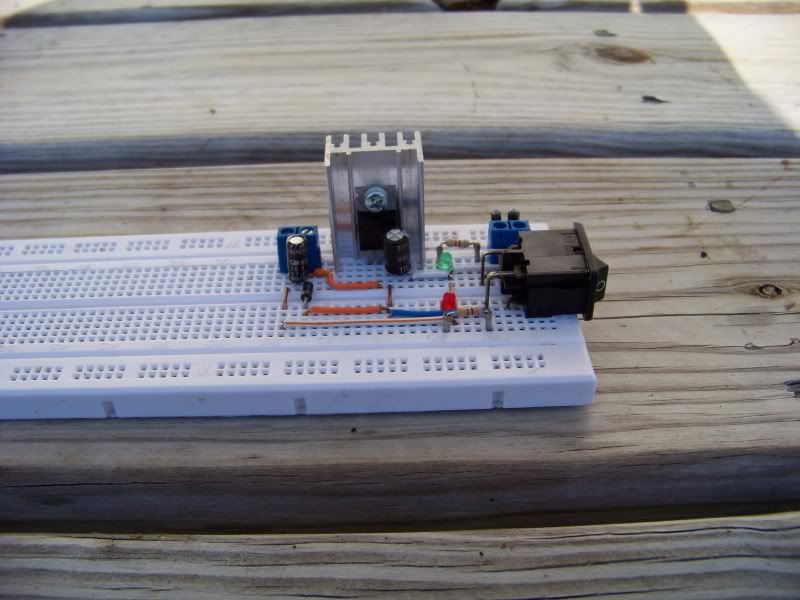
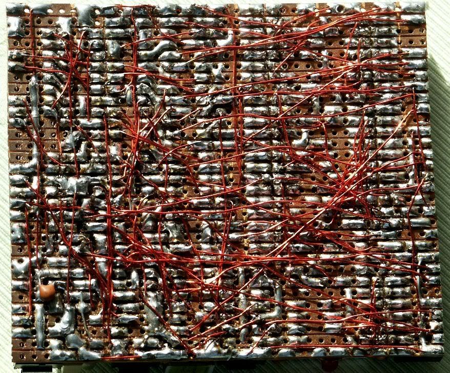
My prototype DIY linear breadboard driver the "Evil Drive v1.0"... whatcha think?
Ok so I got a wild hair up my arse the other night and decided to whip together a linear driver out of scavenged spare parts. Of all the linear drives I have seen the are all a giant clusterhump of tangled wires... you cant tell what goes where. So I decided to come up with my own layout. This is a prototype, mainly just to figure out how I was going to lay out the circuit. Everything but the breadboard, the LM317, and the terminal blocks. Later on I plan on putting a 1084 or other IC on there (I found one on there with a mere 400mv dropout... this opens the door to some interesting power possibilities. I hope to run it off of a 9v switch mode wall wart (considering I get them at the local goodwill store all the time for $2 each). So without further ado, here is what I come up with so far:
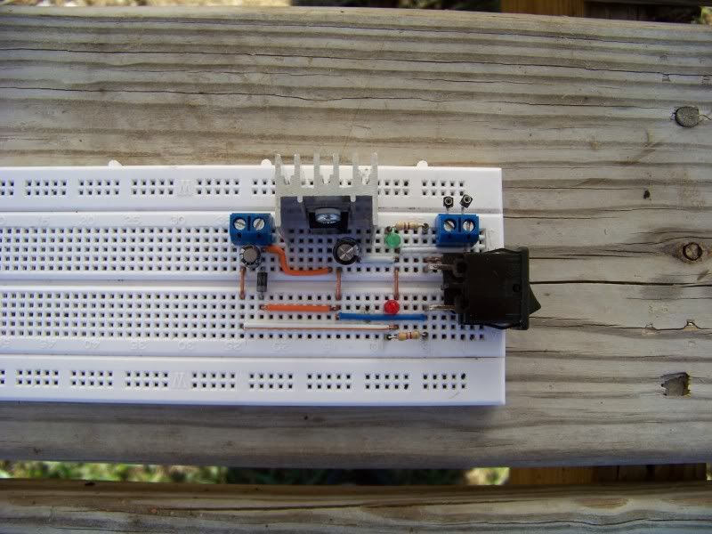
Basically this is your typical linear driver (minus your feedback resistors) except it has several safety features built in not included in some of the other driver designs I have seen.
The first is the green LED. Pretty much simple... dropper resistor connected to the LED. This lets you know right off if your power is connected properly... terminals reversed, no lights.
The second safety feature is the red LED. In addition to letting you know your regulator IC is getting power, it is also a "dump load". Red was specifically chosen since AFAIK, red LED's generally have the lowest forward voltage drop. So, basically as soon as you cut the power off, since it is connected across the terminals of the input filtering cap it drains the cap.
The third safety feature is the IN4001 diode. This is connected to the "IN" pin of the regulator and input filtering cap. During normal circuit operation the input voltage is greater than the output voltage so no current (well maybe other than a little bit of leakage current) flows thru it. But again, as soon as you cut the power the dump load will drain the main cap, the voltage will go down on the primary side, thus allowing current to drain out of the output filter cap potentially saving your laser diode.
I hope I have covered all my bases with this one. I have tried to keep the feedback and filtering caps as close to the applicable components as possible. And yes I will transfer the whole setup to a brand new breadboard prior to testing and use all new components... the breadboard it is on is simply a board that I use to practice my layouts on.
But I still have some questions... how much input and output capacitance is necessary I'm using ultra low ESR capacitors with high ripple current ratings, are tantalums necessary? Currently have 100uf on input filter and 47uf on output, is this overkill or could it handle more? I like the whole idear of having a "soft start" driver.
Wish I had a scope. :cryyy:
Ok so I got a wild hair up my arse the other night and decided to whip together a linear driver out of scavenged spare parts. Of all the linear drives I have seen the are all a giant clusterhump of tangled wires... you cant tell what goes where. So I decided to come up with my own layout. This is a prototype, mainly just to figure out how I was going to lay out the circuit. Everything but the breadboard, the LM317, and the terminal blocks. Later on I plan on putting a 1084 or other IC on there (I found one on there with a mere 400mv dropout... this opens the door to some interesting power possibilities. I hope to run it off of a 9v switch mode wall wart (considering I get them at the local goodwill store all the time for $2 each). So without further ado, here is what I come up with so far:
Basically this is your typical linear driver (minus your feedback resistors) except it has several safety features built in not included in some of the other driver designs I have seen.
The first is the green LED. Pretty much simple... dropper resistor connected to the LED. This lets you know right off if your power is connected properly... terminals reversed, no lights.
The second safety feature is the red LED. In addition to letting you know your regulator IC is getting power, it is also a "dump load". Red was specifically chosen since AFAIK, red LED's generally have the lowest forward voltage drop. So, basically as soon as you cut the power off, since it is connected across the terminals of the input filtering cap it drains the cap.
The third safety feature is the IN4001 diode. This is connected to the "IN" pin of the regulator and input filtering cap. During normal circuit operation the input voltage is greater than the output voltage so no current (well maybe other than a little bit of leakage current) flows thru it. But again, as soon as you cut the power the dump load will drain the main cap, the voltage will go down on the primary side, thus allowing current to drain out of the output filter cap potentially saving your laser diode.
I hope I have covered all my bases with this one. I have tried to keep the feedback and filtering caps as close to the applicable components as possible. And yes I will transfer the whole setup to a brand new breadboard prior to testing and use all new components... the breadboard it is on is simply a board that I use to practice my layouts on.
But I still have some questions... how much input and output capacitance is necessary I'm using ultra low ESR capacitors with high ripple current ratings, are tantalums necessary? Currently have 100uf on input filter and 47uf on output, is this overkill or could it handle more? I like the whole idear of having a "soft start" driver.
Wish I had a scope. :cryyy:
Last edited:


")

")