Welcome to Laser Pointer Forums - discuss green laser pointers, blue laser pointers, and all types of lasers

LPF Donation via Stripe | LPF Donation - Other Methods

Links below open in new window

ArcticMyst Security by Avery

Modern Dummy load

Wmacky

0
Joined
May 4, 2014
Messages
163
Points
0
I just got through reading the older DIY dummy load thread, but didn't see where the design ever got updated. The DIY vesion, along with the current one availble at SL, seem limited to 1 amp draw. I would like an updated version that can handle the latest high power drivers / L diodes. That currently being 3.4 amps? I have a Fluke meter that can read up to 10 Amps max and was considering using that inste4ad og the drop resister. The reason being the added complacation of needing a different Ohm valve due to the additional current draw. Is that right? Changing the ohm valve then prohibs a quick easy translation from Mv to MA.

Thought on that? For the Diode I was thinking about using a 4 amp diode in a TO-220 package and mounting them on a long heat sink? Would these work?

C3D04065A - CREE C3D04065A - SIC SCHOTTKY DIODE, 4A, 650V, TO-220 | Newark element14 US


Is there better options? Why hasn't anyone updated the older design?
 
Last edited:


Wmacky

0
Joined
May 4, 2014
Messages
163
Points
0
Well I did seach, and read many threads but seemed to have missed that one. I'll check it out now...
 
Last edited:

djQUAN

0
Joined
May 27, 2013
Messages
1,154
Points
63
to the OP.

The diode you listed is a schottky type which has a lower forward voltage drop which isn't suitable (you can use more to get the same Vf but that gets expensive) plus that's a silicon carbide diode which is pretty pricey for what you intend to use it for.
 

Wmacky

0
Joined
May 4, 2014
Messages
163
Points
0
Thanks for the links, and diode info. Looks like they are a bad choice!

Yeah, I'm still reading, but may take the easy path and go with Jufran88's board. I thought it was a 1 amp board, but 3 amps is much better. Still that leaves a hole for the drivers for the latest 445. I guess even with a heatsink slapped on top it won't handle 3.4 very well.

I wonder if I could utlize the board and upgrade componets to 4 amp duty. Not much room for additional heatsinks! RHD, I wish you ordered extra boards, or did you..............:)
 
Last edited:

rhd

0
Joined
Dec 7, 2010
Messages
8,475
Points
0
I wonder if I could utlize the board and upgrade componets to 4 amp duty. Not much room for additional heatsinks! RHD, I wish you ordered extra boards, or did you..............:)

You're welcome to make some of my boards. I actually improved the design a bit, but never bothered ordering the improved version myself.

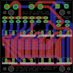
The improved version puts the resistor IC in line with the diodes physically, so that they're easier to heatsink (and there are now only 7 diodes instead of 8). It also staggers the diodes between rows, so that if you're only using 4 diodes, it uses 2 diodes in each row, instead of 4 diodes in one row and none in the other. This makes for better heat dissipation.

This is the diode used: Digikey

And even though the board itself suggests using a 1 ohm resistor, I would strongly suggest moving to a 0.1 ohm resistor instead. It doesn't really make the conversion hard (just move a decimal place in your head), and it saves you from dropping 4V over the resistor when you're testing 4A, etc. That's a lot of voltage drop.

attachment.php


attachment.php
 

Attachments

  • High Current Test Load V08.zip
    6.6 KB · Views: 40
  • Board V08.png
    Board V08.png
    46.2 KB · Views: 1,214
  • Schematic V08.png
    Schematic V08.png
    4.5 KB · Views: 1,438
Last edited:

Wmacky

0
Joined
May 4, 2014
Messages
163
Points
0
You're welcome to make some of my boards. I actually improved the design a bit, but never bothered ordering the improved version myself.

The improved version puts the resistor IC in line with the diodes physically, so that they're easier to heatsink (and there are now only 7 diodes instead of 8). It also staggers the diodes between rows, so that if you're only using 4 diodes, it uses 2 diodes in each row, instead of 4 diodes in one row and none in the other. This makes for better heat dissipation.

This is the diode used: Digikey

And even though the board itself suggests using a 1 ohm resistor, I would strongly suggest moving to a 0.1 ohm resistor instead. It doesn't really make the conversion hard (just move a decimal place in your head), and it saves you from dropping 4V over the resistor when you're testing 4A, etc. That's a lot of voltage drop.

attachment.php


attachment.php

Thanks for all that!. Nevr had a board made. I wonder the time involved and minumium number. I'm very intriged! Thanks again.
 

rhd

0
Joined
Dec 7, 2010
Messages
8,475
Points
0
Thanks for all that!. Nevr had a board made. I wonder the time involved and minumium number. I'm very intriged! Thanks again.

If you use Oshpark, the time involved is about 2 minutes once you have the board file. The cost on a board like that would be around $7, and they'd make you order 3 - so basically a $20 investment. Roughly.
 
Joined
Feb 25, 2010
Messages
1,643
Points
113
If you use Oshpark, the time involved is about 2 minutes once you have the board file. The cost on a board like that would be around $7, and they'd make you order 3 - so basically a $20 investment. Roughly.

MMMmmm..Wmacky..I am interested in one of these !!!!! !!!!!!!!! RHD...Thanx. for the design !!!

Lite'em Up CDBEAM=======>
 
Last edited:

Wmacky

0
Joined
May 4, 2014
Messages
163
Points
0
If you use Oshpark, the time involved is about 2 minutes once you have the board file. The cost on a board like that would be around $7, and they'd make you order 3 - so basically a $20 investment. Roughly.

I just ordered the boards HAHA :D Do you have BOM? I guess Other than the diodes, I just need the Resistor, and jumper pins?
 
Last edited:

rhd

0
Joined
Dec 7, 2010
Messages
8,475
Points
0
Basically just need the diodes I linked, plus resistor, headers and jumpers (take a look at the schematic image for part numbers - but grab a different resistor - if you want 0.1 ohm - just find a high wattage 0.1 ohm TO-220 resistor - digikey has them)

You might want to think about something to use as a heatsink.
 
Last edited:

Wmacky

0
Joined
May 4, 2014
Messages
163
Points
0
Basically just need the diodes I linked, plus resistor, headers and jumpers (take a look at the schematic image for part numbers - but grab a different resistor - if you want 0.1 ohm - just find a high wattage 0.1 ohm TO-220 resistor - digikey has them)

You might want to think about something to use as a heatsink.

Great thanks! A rep to you!
 
Last edited:

Wmacky

0
Joined
May 4, 2014
Messages
163
Points
0
The boards arrived already, and look great. Though I have bought lots of custom made boards for various hobbies, I've never had any made myself. Much cheaper, and easier than expected, as long as you have a designer giving yo files to use! Have these prices dropped recently? Anyway, I still need to order componets next.
 
Joined
Sep 20, 2013
Messages
17,445
Points
113
Yeah, I have several, but the one I use the most is ten 10 amp rectifiers and a 1 ohm 1% resistor for quick measurements. I also have others, using 1 amp rectifiers and 3 amp rectifiers. If I am using a drive that uses a high output current and voltage I omit the resistor and connect one of my ammeters in series with the load. When in doubt, just measure the output voltage of the driver and add or omit rectifiers as needed.


Top