Welcome to Laser Pointer Forums - discuss green laser pointers, blue laser pointers, and all types of lasers

Buy Site Supporter Role (remove some ads) | LPF Donations

Links below open in new window

FrozenGate by Avery

Microboost Grounding

Joined
Jan 8, 2009
Messages
3,144
Points
83
I have been researching the microboost and have some questions. For a flex V5 build, I fold the case pins and use case - for my build.

Now I've seen pics and read where the microboost has a floating -. I was wanting some alternative so I don't need to run the - from the batt. pad on the driver to the case- pin on the diode. Any help will be much app. jander6442


Do NOT attach the case pin to the negative pin. Leave it free.

Just connect the case pin to the INPUT (battery) side of the driver and you can use the case/host body as the negative path

It is just a short wire. Am I missing the problem?

Peace,
dave

**EDIT** The negative input is also available along the side where the negative trace is bared for one of the "range" jumpers
 
Last edited:
Thanks dave, I know it is just a short wire... Just trying to keep the area as clean as possible.

I've always been a little mental about keeping builds as clean as possible in that area.

Not the perfectionist in me, just a habit I've seemed to have fallen into.

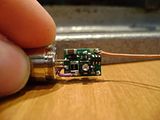
this is a pic from forum member ReNNo


Not to say his isn't tighty. I am less thrilled about the wire though.:tinfoil::undecided:
 
He just soldered it to that pin because it was easy. If you want to try to make the connection to another metal part of the host, go for it. It will probably be less "tidy," though. Just make sure it is electrically continuous to the switch or - connection if the switch is on the + side.


Back
Top